Test Procedures
A recommended method for performing the FVT is described by ASTM in standard test method D2573-08 Standard Test Method for Field Vane Shear Test in Cohesive Soil. The International Organization for Standardization (ISO) also provides a recommended standard for FVTs ISO/DIS 22476-9. The test is performed by first inserting the vane to the desired test depth using one of the procedures described or other suitable technique. In the case where a borehole or a protective vane housing is used, it is recommended by the ASTM standard that the hole or housing should be no closer than five borehole diameters or five vane housing diameters from the test location. This provision is given to reduce disturbance effects from drilling. It is further suggested that the vane should be inserted in a single thrust without applying torque to the vane rods. No recommendation is given for rate of installation. It is recommended that tests be performed at intervals of not less than 0.61m (2 ft) throughout the soil profile, except when a very small vane is used.
Once the vane is in position, torque is applied to the vane at a rate not to exceed 0.17s (67min). ASTM D2573 specifies that the waiting time between inserting the vane and beginning rotation should be no more than 5 min. Normally, the test should be performed within about 1-2 min after the installation. Using the recommended rate of vane rotation of 0.17s will give a time to reach peak torque ranging from 2 to 5 min except in very soft plastic clays where the time to failure may be more in the order of 10-15 min. In brittle soils that reach peak strength at very low strain levels, failure may occur very quickly.
After the maximum torque has been obtained, ASTM D2573 recommends that the rods be rotated a minimum of ten revolutions to remold the soil. Within about 1 min after this remolding process, the remolded strength is obtained by rotating the vane in the same manner as used to obtain the peak strength. Remolded strengths, sur, are used along with peak strength measurements, su, to provide an indication of soil sensitivity, S„ as follows:

Factors Affecting Test Results
Several factors can affect the results obtained with the FVT and therefore can affect the interpretation of the undrained shear strength value obtained. These factors include both variations in the equipment used and variations in the test procedure.
Installation Effects
Disturbance
Insertion of the vane causes some degree of disturbance in nearly all soils. The degree of fabric disturbance may depend on the specific geometry of the vane and other components (i.e., blade thickness, diameter, rod size, etc.) and is also related to soil properties such as stress history, plasticity, and sensitivity. Disturbance occurs because a finite amount of soil must be displaced in order to allow the vane to occupy that space. Disturbance created by inserting the vane may also be expected to be greater for soils with high sensitivity.
Photographic observations of fabric disturbance by vane insertion and rotation (e.g., Arman et al. 1975; Chandler 1988; Roy & Leblanc 1988) indicate that the area of disturbance is comparable to that postulated by Cadling & Odenstad (1950). It may be that the most significant consequence of fabric disturbance is that the actual failure surface produced by the vane is somewhat larger than the vane itself. This is likely to be more significant in stiff overconsolidated clays and clays of low plasticity. The effective diameter of the failure surface appears to be about 5% larger than the vane in these soils. This would lead to a direct decrease in the estimated shear strength of about 16%.
Disturbance produced by inserting a vane should relate to the geometry of the vane for the same soil. The more soil that must be displaced to allow the vane to be inserted, the more the amount of disturbed soil. Thicker blades on the vane will produce more disturbance for a vane with a constant diameter. Similarly, vanes with the same blade thickness but different diameters should show less disturbance effects as the diameter increases. In order to rationally quantify the level of disturbance caused by the vane, Cadling & Odenstad (1950) suggested using the term “perimeter ratio”, illustrated in Figure 5.6 and defined as follows:
a = 4e/JtD (5.2)
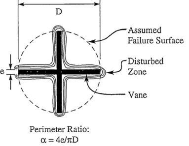
where
a = perimeter ratio (usually expressed as %) e = thickness of vane blade D = diameter of vane.
If the zone of disturbed soil adjacent to the vane blades is related to the blade thickness, then for the same diameter vane, a larger amount of undisturbed soil for testing will result from using a vane with thinner blades. The undrained strength measurement from a thinner vane should be more representative of undisturbed conditions. Equation 5.2 suggests that in order to reduce disturbance effects, either the blade thickness should be reduced, or the vane diameter must be increased, or both. Typical commercial vanes have perimeter ratios in the range of 4%-8%. The perimeter ratios for the recommended vane dimensions given in Table 5.1 range from 4.0% to 6.4%
La Rochelle et al. (1973) illustrated the influence of vane perimeter ratio on the resulting strength profiles obtained in sensitive Champlain Sea clay (St =12) by using vanes of the same diameter but different blade thicknesses. The resulting strength profiles are shown in Figure 5.7 and show that for most of the tests, the measured undrained shear strength increases as the vane blade thickness decreases, i.e., as a decreases.
By assuming that the true in situ undisturbed strength would be represented by a vane with a blade thickness of 0 (i.e., a = 0), the results presented in Figure 5.7 were used to extrapolate the measured undrained strength to a blade thickness of zero or “zero disturbance”, as shown in Figure 5.8. An increase in the estimated undisturbed strength over the measured value using a vane with a = 5% of about 15% is indicated. Similar results have been presented by Roy & Leblanc (1988) for sensitive marine clay in Canada (St = 4-14) and Cerato & Lutenegger (2004) for varved clay in Massachusetts (St = 4-6) as shown in Figure 5.9. Results from these studies suggest that the extrapolation to zero disturbance can result in an increase in estimated shear strength in the order of 10%—15% over a vane with a = 5%. That is, a conventional vane gives a strength about 10%—15% lower than the true undisturbed strength simply because of disturbance from insertion.
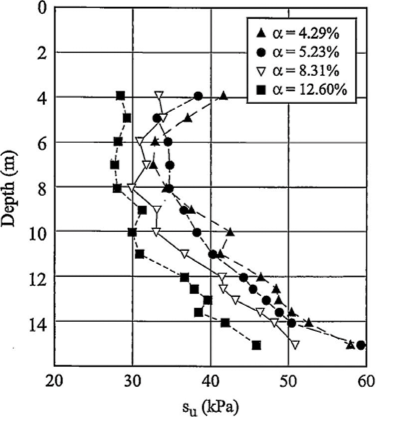
Figure 5.7 Influence of perimeter ratio (disturbance) on measured shear strength. (After La Rochelle et al. 1973.)
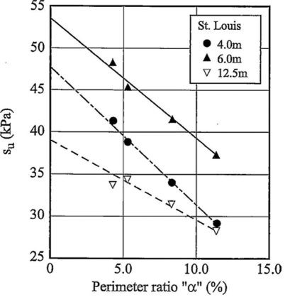
Figure 5.8 Extrapolation of vane data with different values of perimeter ratio to vane of zero blade thickness to estimate undisturbed strength. (After La Rochelle et al. 1973.)
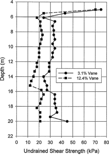
Figure 5.9 Influence of vane area ratio on measured undrained shear strength.
Insertion Pore Water Pressures
In addition to producing soil disturbance in the vicinity of the vane blades, inserting the vane in saturated clays is assumed to occur under undrained conditions. The insertion of the vane produces a change in the effective stress field surrounding the vane. Several laboratory studies using instrumented vanes have shown that significant excess pore water pressures can be generated during vane insertion in both natural and reconstituted soft clays (e.g., Matsui 8c Abe 1981; Kimura 8c Saitoh 1983; Roy 8c Mercier 1989). The magnitude of generated pore water pressure is in the order of 0.5-0.75ovo'. These studies have also shown that there is very little dissipation of excess pore water pressure in the normal waiting time between insertion of the vane and the start of the vane rotation. It was observed that complete dissipation of the excess pore water pressure required as much as four to five hours, as discussed further in Section 5.6.2.

