Test Procedures
Unlike the DMT, which is pushed into the ground in a continuous manner without drilling a borehole, spade cells are typically installed at the bottom of a drilled hole. The reason for this is mostly practical as experience has shown that if the spade is pushed more than 1-1.5 m (3-5 ft) ahead of hole, there is a high probability of damage to the blade from bending. This means that in order to use the blade as a profiling tool, the testing will need to be planned out over several days or weeks, with the spade removed and borehole advanced only after the test has been completed by achieving an equilibrium stress. The final response varies with soil stiffness and is fastest for very stiff clays, on the order of several hours to one day, and slowest for very soft clays, on the order of several weeks.
In normal operation, the spade is pushed hydraulically into the ground at the base of the borehole and is never driven. Immediately after insertion, the test clock begins so that time zero for the test is the time that pushing stops and the load is removed. The pressure in the transducer is recorded at relatively close intervals at the beginning of the test and at progressively increasing intervals as the test proceeds. In the case of tests performed in soft clays, where it may take several weeks to obtain the final response, pressure readings every day or every other day are typical after obtaining the initial response throughout the first day.
After removing the spade from the test zone at the completion of the test, the blade is cleaned off and a zero reading obtained so that each test will have a before and after test zero reading. This will alert the operator of any potential problems with the cell. Cells are normally calibrated in a pressure chamber by the manufacturer.
Results and Interpretation
Since the test data obtained are total soil stress over time, the results of individual tests are normally presented graphically as shown in Figure 10.14. The test data shown in Figure 10.14 were obtained by the author at a clay site with OCR decreasing with depth. The curves all show a similar response and are generally “S” shaped when presented on a semi-log plot. These curves are similar to DMT “A” dissipation tests described in Chapter 6. The response for equilibrium is much faster in the overconsolidated zone than in the normally consolidated zone, which is to be expected. In this case, since the soil is a varved clay deposit with silt lenses and a relatively high horizontal hydraulic conductivity (10-6 cm/s), the final response in the soft clay occurs relatively fast, i.e., on the order of one week.
The equilibrium or final value of total horizontal stress is denoted as chf and is used to define the horizontal stress ratio as:

where
^—consolidated lateral earth pressure coefficient uB=in situ pore water pressure at the test depth o'vo=in situ vertical effective stress at the test depth

Figure 10.14 Typical push-in earth pressure cell test results.
The term Kc is used in Equation 10.1 and not K„, the at-rest coefficient of earth pressure since the test measures the total lateral stress after insertion of a flat blade. The two terms should not be considered the same. Tedd & Charles (1981) suggested that a simple empirical correction factor could be applied to chf to obtain oho. Based on a series of tests where spades were used under known stress conditions, it was suggested that a stress equal to one-half of the undrained shear strength (0.5 s„) should be subtracted from the measured final total stress to account for the overstress created by inserting the blade. These data are shown in Figure 10.15. An updated summary of the available test data presented by Tedd et al. (1989) shows more scatter, which may be partly related to the selection of su and partly related to the reference test used for the true reading.
Ryley & Carder (1995) showed that for clays with undrained shear strength in the range of 70-150 kPa (1500-3000 psf), a more reasonable correction for the overstress would be 0.8 su. The use of a correction factor of 0.5 su would be conservative for retaining walls as it would give higher stresses than may actually be present. On the other hand, this would be unconservative for the design of driven piles, suggesting lateral stresses that are higher than actual values.
A more direct approach to evaluating the results of spade cell tests may be to develop a functional relationship between Kc and K„. Results taken from the literature for a number of different test sites and tests conducted by the author are shown in Figure 10.16 and demonstrate that Kc is related to the stress history through OCR. The scatter in the reported results is probably related to differences in blade geometry as previously discussed. Even for OCR=l, there is scatter in the test results. For a given clay, under simple unloading, there is a relationship between K() and OCR (e.g., Mayne &c Kulhawy 1982). Therefore, it is a relatively simple matter to establish a relationship between Kc and K() since both appear to be related to OCR.
Spade cells should be considered as an adjunct testing program to provide additional test data for determining horizontal stresses in fine-grained soils. The tests are relatively inexpensive, easy to perform, and generally provide the reliable test data. On large projects
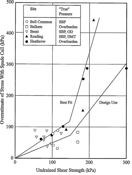
Figure 10.15 Overstress from push-in earth pressure cells as a function of undrained shear strength. (After Ryley & Carder 1995.)

Figure 10.16 Results of push-in earth pressure cells as a function of soil OCR.
where the at-rest horizontal stress or K„ is of significant importance to the project, several approaches using both in situ and laboratory tests will likely be used. In conjunction with Dilatometer Tests, Pressuremeter Tests, or HFTs, the use of push-in spade cells is an attractive alternative.

