Nonimaging Optical Systems and Their Uses
Nonimaging Collectors
Nonimaging concentrators and illuminators have several current and some potential applications. It is best to explain the general concept of a nonimaging concentrator by highlighting one of its applications: the utilization of solar energy. The radiation power density received from the sun at the earth’s surface, often denoted by S, peaks at approximately 1 kW/m2, depending on many factors. If we collect this power by absorbing it on a perfect blackbody, the equilibrium temperature T of the blackbody will be given by[1]

where a is the Stefan Boltzmann constant, 5.67 x 10~8 Wm~2 K~4. In this example, the equilibrium temperature would be 364°K, or just below the boiling point of water. For many practical applications of solar energy this is sufficient, and many systems for domestic hot water heating based on this principle are available commercially for installation in private dwellings. However, for larger scale purposes or for generating electric power, a source of heat at 364°K has a low thermodynamic efficiency, since it is not practicable to get a very large temperature difference in whatever working fluid is being used in the heat engine. If we wanted, say, >300°C—a useful temperature for the generation of motive power—we would need to increase the power density 5 on the absorbing blackbody by a factor C of about 6 to 10 in Equation (1.1). This, briefly, is one use of a concentrator—to increase the power density of solar radiation. When it is stated plainly like that, the problem sounds trivial. The principles of the solution have been known since the days of Archimedes and his burning glass:4 we simply have to focus the image of the sun with an image-forming system—a lens—and the result will be an increased power density. The problems to be solved are technical and practical, but they also lead to some interesting pure geometrical optics. The first question is that of the maximum concentration: how large a value of C is theoretically possible? The answer to this question is simple in all cases of interest. The next question—can the theoretical maximum concentration be achieved in practice?—is not as easy to answer. We shall see that there are limitations involving materials and manufacturing, as one would expect. But there are also limitations involving the kinds of optical systems that can actually be designed, as opposed to those that are theoretically possible. This is analogous to the situation in classical lens design. The designers sometimes find that a certain specification cannot be fulfilled because it would require an impractically large number of refracting or reflecting surfaces. And sometimes they do not know whether it is in principle possible to achieve aberration corrections of a certain kind.
The natural approach of the classical optical physicist is to regard the problem as one of designing an image-forming optical system of a very large numerical aperture—that is, a small aperture ratio or/-number. One of the most interesting results to have emerged in this field is a class of very efficient concentrators that would have very large aberrations if they were used as image-forming systems. Nevertheless, as concentrators, they are substantially more efficient than image-forming systems and can be designed to meet or approach the theoretical limit. We shall call them nonimaging concentrating collectors, or nonimaging concentrators for short. Nonimaging is sometimes substituted by the word anidolic (from the Greek, meaning “without image”) in languages such as Spanish and French because it’s more specific. These systems are unlike any previously used optical systems. They have some of the properties of light pipes and some of the properties of image-forming optical systems but with very large aberrations. The development of the designs of these concentrators and the study of their properties have led to a range of new ideas and theorems in geometrical optics. In order to facilitate the development of these ideas, it is necessary to recapitulate some basic principles of geometrical optics, which is done in Chapter 2. In Chapter 3, we look at what can be done with conventional imageforming systems such as concentrators, and we show how they necessarily fall short of ideal performance. In Chapter 4, we describe one of the basic nonimaging concentrators, the compound parabolic concentrator, and we obtain its optical properties. Chapter 5 is devoted to several developments of the basic compound parabolic concentrator: with plane absorber, mainly aimed at decreasing the overall length; with nonplane absorber; and with generalized edge-ray wave fronts, which is the origin of the tailored designs. In Chapter 6, we examine in detail the flowline approach to nonimaging. Chapter 7 will be about the exposition of the emerging field of freeform optics. Chapter 8 is about the wave description of the optical measurements.
Failure of Imaging Optics
An example of the failure of imaging optics to confront real-world situations is shown in Figure 1.1. The point object A is at the center of a spherical reflecting cavity and is also one focus of an elliptical reflecting cavity. The point object В is at the other focus. If we start A and В at the same temperature, the probability of radiation from В reaching A is clearly higher than A reaching B. So we conclude that A warms up while В cools off, in violation of the second law of thermodynamics. The paradox is resolved by making A and В extended objects, no matter how small. In fact, a physical object with temperature has many degrees of freedom and cannot be pointlike. Then, the correct cavity is not elliptical, but a nonimaging shape that ensures an efficient equal radiation transfer between A and B.[2] It is worth mentioning that the

FIGURE 1.1 The ellipse paradox: the ellipse images “point” object В (right) at “point” object A (left) “perfectly” and the sphere images A on itself “perfectly.”
correct nonimaging design does not converge into the ellipse/sphere configuration at the limit, i.e. zero, toward which the size of A and В tend.
Definition of the Concentration Ratio; the Theoretical Maximum
From the simple argument in Section 1.1 we see that the most important property of a concentrator is the ratio of area of input beam divided by area of output beam; this is because the equilibrium temperature of the absorbing body is proportional to the fourth root of this ratio.
We have denoted this ratio by C and called it the concentration ratio. Initially, we modeled a concentrator as a box with a plane entrance aperture of area A and a plane exit aperture of area A' that is just large enough to allow all transmitted rays to emerge (see Figure 1.3). Then the concentration ratio is

Consider the following problem described in Figure 1.2, a design that maximizes the temperature of the absorber T}, while maintaining the source at 7) (a heat reservoir,
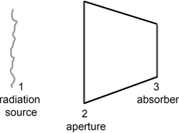
FIGURE 1.2 A schematic of the general concentrator problem.

FIGURE 1.3 Schematic diagram of a concentrator. The input and output surfaces can face in any direction; they are drawn in the figure so both can be seen. It is assumed that the aperture A is just large enough to permit all rays passed by the internal optics that have entered within the specified collecting angle to emerge.
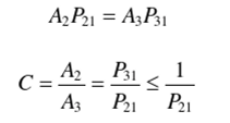
like the sun), and introducing probabilities P,; where Pl3 is the probability of radiation from wall l reaching wall 3, and so on. The condition is PM = 1. In cases where P33 is not 0 (as in a cavity receiver) the generalization is P31 = 1 - P33 which still maximizes P3i. These conditions are intuitively self-evident. Here we sketch a proof: if P3, < 1, then some energy, say P3l, is exchanged with a body x which is, in general, at a lower temperature than the source 1. Therefore, at equilibrium, Ti will reach a temperature intermediate between 7j and Tx. Stated the other way, if P3 reaches 7j at equilibrium, then all the energy exchange must be between A, and A, since the other objects will in general be at a lower temperature. Additionally, for an efficient concentrating system (P|2=P13) the concentration value is 1/P21. In the case of photovoltaic systems, the condition states that light starting from the solar cell would invariably reach the source. The application of this concept should lead to the development of more thermodynamically efficient thermal designs as well as higher efficiency solar cells.
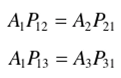
In other words, the second law guarantees;
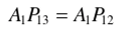
In a lossless system, the first law or energy conservation guarantees:
Therefore,
In the preceding definition, it was tacitly assumed that compression of the input beam occurred in both the dimensions transverse to the beam direction, as in ordinary lens systems. In solar energy technology there is a large class of systems in which the beam is compressed in only one dimension. In such systems all the operative surfaces, reflecting and refracting, are cylindrical with parallel generators (but not in general circular cylindrical). Thus, a typical shape would be a parabolic trough, with the absorbing body lying along the trough. Such long trough collectors have the obvious advantage of not needing to be guided to follow the daily movement of the sun across the sky. The two types of concentrator are sometimes called three- and two-dimensional, or 3D and 2D, concentrators. The names 3D and 2D are also used in this book to denote that the optical device has been designed in 3D geometry or in 2D geometry (in the latter case, the real concentrator, which of course exists in a 3D space, is obtained by rotational or translational symmetry from the 2D design). In these cases we will use the name 2D design or 3D design to differentiate from a 2D or a 3D concentrator. The 2D concentrators are also called linear concentrators. The concentration ratio of a linear concentrator is usually given as the ratio of the transverse input and output dimensions, measured perpendicular to the straight-line generators of the trough. The question immediately arises whether there is any upper limit to the value of C, and we shall see that there is. The result, proved later, is very simple for the 2D case and for the 3D case with an axis of revolution symmetry (rotational concentrator). Suppose the input and output media both have a refractive index of unity, and let the incoming radiation be from a circular source at infinity subtend a semiangle вг Then the theoretical maximum concentration in a rotational concentrator is

Under this condition the rays emerge at all angles up to л/2 from the normal to the exit face, as shown in Figure 1.3. For a linear concentrator the corresponding value will be l/sint?,. The next question that arises is, can actual concentrators be designed with the theoretically best performance? In asking this question we make

FIGURE 1.4 Incident and emergent ray paths for an ideal 3D concentrator with symmetry about an axis of revolution. The exit aperture diameter is sin0, times the exit aperture diameter; the rays emerge from all points in the exit aperture over a solid angle 2Ik.
certain idealizing assumptions—for example, that all reflecting surfaces have 100% reflectivity, that all refracting surfaces can be perfectly antireflection-coated, that all shapes can be made exactly right, and so forth. We shall then see that the following answers are obtained: (1) 2D concentrators can be designed with the theoretical maximum concentration; (2) 3D concentrators can also have the theoretical maximum concentration if they use variable refractive index material or a pile of infinitely thin surface waveguides, properly shaped; and (3) some rotational symmetric concentrators can have the theoretical maximum concentration. In case (3) it appears for other types of design that it is possible to approach indefinitely close to the theoretical maximum concentration either by sufficiently increasing the complexity of the design or by incorporating materials that are in principle possible but in practice not available. For example, we might specify a material of very high refractive index—say, 5—although this is not actually available without large absorption in the visible part of the spectrum.
Uses of Concentrators
This application of concentrators as solar energy amplifiers has, of course, stimulated great developments in the design and fabrication of concentrators. But it is by no means the only application. The particular kind of nonimaging concentrator that has given rise to these great developments was originally conceived as a device for collecting as much light as possible from a luminous volume (the gas or fluid of a Cerenkov counter) over a certain range of solid angles and sending it onto the cathode of a photomultiplier. Since photomultipliers are limited in size and since the volume in question was of order 1 m3, this is clearly a concentrator problem (Hinterberger & Winston, 1966a,b).
Subsequently the concept was applied to infrared detection (Harper et al., 1976), where it is well known that the noise in the system for a given type of detector increases with the surface area of the detector (other things being equal).
Uses of Illuminators
Nonimaging collectors are also used in illumination. The source (a filament, an LED, etc.) in general emits in a wide angular spread at low intensity, and the problem consists of designing an optical device that efficiently collimates this radiation so it is emitted in a certain angular emitting region, which is smaller than the angular emitting region of the source. The problem is conceptually similar to the concentrating problem, substituting aperture areas for angular region sizes. We will see soon that both statements are equivalent (Figure 1.4).
References
Harper, D. A., Hildebrand, R. H., Pernic, R., and Platt, R. (1976). Heat trap: An optimised far infrared field optics system. Appl. Opt. 15, 53-60.
Hinterberger, H„ and Winston, R. (1966a). Efficient light coupler for threshold Cerenkov counters. Rev. Sci. lustrum. 37, 1094-1095.
Hinterberger, H., and Winston, R. (1966a). Gas Cerenkov counter with optimized light-col- lection efficiency. Proc. hit. Conf. Instrum. High Energy Phys. 205-206.
Winston, R., and Enoch, J. M. (1971). Retinal cone receptor as an ideal light collector. J. Opt. Soc. Am. 61. 1120-1122.
- [1] Ignoring various factors such as convection and conduction losses and radiation at lower effectiveemissivities. f For an amusing argument concerning the authenticity of the story of Archimedes, see Stavroudis(1973).
- [2] The Ellipsoid Paradox in Thermodynamics, W. T. Welford and R. Winston, Journal of StatisticalPhysics, Vol. 28, No 3, 1982

