Developments and Modifications of the Compound Parabolic Concentrator
Introduction
There are several possible ways in which the basic CPC as described in Chapter 4 could be varied for specific purposes. Some of these have been mentioned already, such as a solid dielectric CPC using total internal reflection. Others spring to mind fairly readily for specific purposes, such as collecting from a source at a finite distance rather than at infinity. In this chapter we describe these developments and discuss their properties.
The Dielectric-Filled CPC with Total Internal Reflection
Both 2D and 3D CPCs filled with dielectric and using total internal reflection were described by Winston (1976). If we consider either the 2D case, or meridian rays in the 3D case, we see that the minimum angle of incidence for rays inside the designcollecting angle occurs at the rim of the exit aperture, as in Figure 5.1. If the dielectric has refractive index n, the CPC is, of course, designed with an acceptance angle в' inside the dielectric, according to the law of refraction. It is then easy to show that the condition for total internal reflection to occur at all points is

Since the sine function can only take values between 0 and 1, the useful values of n are greater than . This is in good agreement with the range of useful optical materials in the visible and infrared regions. In a 3D CPC, rays outside the meridian plane have a larger angle of incidence than meridian rays at the same inclination to the axis so Eq. (5.1) covers all CPCs. The expressions in Eq. (5.1) are plotted in Figure 5.2. For most purposes it is unlikely that collecting angles exceeding 40° would be needed, so the range of useful n coincides very well. For trough collectors there is always total internal reflection at the perpendicular end walls, since there is the same angle of incidence here as for the ray at & at the entry aperture on the

FIGURE 5.1 A dielectric-filled compound parabolic concentrator. The figure is drawn for an sentry angle of 18° and a refractive index of 1.5. The concentration ratio is thus 10.2 for a 3D concentrator.
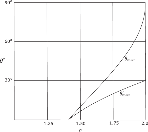
FIGURE 5.2 The maximum collecting angles for a dielectric-filled CPC with total internal reflection, as functions of the refractive index.
curved surface. In fact, it could be shown that for n > -Jl it is impossible for a ray to get into a trough CPC and not be totally internally reflected at the end face.
The angular acceptance of the dielectric-filled 2D CPC for nonmeridional rays is actually larger than a naive analogy with the n= 1 case would indicate. To see this, it is convenient to represent the angular acceptance by the direction cosine variables introduced earlier. Let x be transverse to the trough, let у lie along the trough, and let L and M be the corresponding direction cosines. We recall that the ordinary (n= 1) 2D CPC accepts all rays whose projected angles in the x, z plane are < the design cutoff angle. This condition is represented by an ellipse in the L, M plane with semidiameters sin 0, and 1, respectively (shown in Figure 5.3a). Therefore, the acceptance

FIGURE 5.3 Angular acceptance for dielectric-filled concentrators, plotted in direction cosine space.
figure just inside the dielectric is such an ellipse with semidiameters sin 0, and a. In terms of direction cosines, Snell’s law is simply

so one might expect the acceptance ellipse in the L, M plane to be scaled up by n. However, the physical values of L and M lie inside the unit circle

It follows that the accepted rays lie inside the intersection of the scaled-up ellipse and the unit circle. This region, as seen in Figure 5.3b, is larger than an ellipse with semidiameters sin 0/ and 1, respectively. A quantitative measure of this enhancement is useful in discussing the acceptance of such systems for diffuse (i.e., totally isotropic) radiation. Diffuse radiation equal-populates phase space. Hence, it is uniformly distributed in the L, M plane. The area of the acceptance figure for an ordinary 2D CPC (corresponding to Figure 5.3a) is n sin ft,. Therefore, the fraction of diffuse radiation accepted is just sin 0,. However, for the dielectric-filled case, the area depicted by Figure 5.3b is found to be

where 0C is the critical angle siir'fl/n). This exceeds л-sin 0, by a factor
 This enhancement factor assumes the limiting value for small angles 0,

and slowly decreases to unity as 0, increases to л/2. For example, for n -1.5, a value typical for plastics, the enhancement is al.17 for small 0, (<10°) and reduces to -1.13 for 0,=4O°. We shall return to this property in Chapter 13, where this extra angular acceptance is shown to be advantageous for solar energy collection.
The dielectric-filled CPC has certain practical advantages. Total internal reflection is 100% efficient, whereas it is difficult to get more than about 90% reflectivity from metallized surfaces. Also, for the same overall length the collecting angle in air is larger by the factor n, since Equations (4.1)—(4.4) for the shape of the CPC would be applied with the internal maximum angle 0/, instead of 0r If the absorber can be placed into optical contact with the exit face and if it can utilize rays at all angles of incidence, the maximum theoretical concentration ratio becomes, from Equation (2.13), n2/sin20,—that is, it is increased by the factor n2 (or л for a trough concentrator).
However, if the rays had to emerge into air at the exit aperture, it is clear that many would get turned back at this interface by total internal reflection. Thus, the CPC design needs to be modified for this case.
The CPC with Exit Angle Less Than π/2
There may well be instances such as that mentioned at the end of the last section where it is either impossible or inefficient to use rays emerging at up to nil from the normal to the exit aperture. The CPC designs can be easily modified to achieve this. It would then be close to being what we have called an ideal concentrator but without maximum theoretical concentration ratio.
Let 0, be the input collecting angle 0O and the maximum output angle. Then an ideal concentrator of this kind would, from Equation (2.18), have the concentration ratio

for a 2D system or

for a 3D system. Following Rabl and Winston (1976) we may call this device a 0/0„ transformer or concentrator. It is convenient to design the a 0/0n concentrator by starting at the exit aperture and tracing rays back. As for the basic CPC we start by considering the 2D case or the meridian rays for the 3D case. Let QQ'=2a' be the exit aperture in Figure 5.4. We make all reversed rays leaving any point on QQ' at angle 0„ appear in the entrance aperture at angle 0, to the axis. This is easily done by
0—0
means of a cone section Q'R making an angle ' ° with the axis. Next, we make
all rays leaving Q at angles less than 0„ appear at the entry aperture at angle 0,; this is done in the same way as for a CPC by a parabola RP' with focus at Q and axis at angle 0, to the concentrator axis. The parabola finishes as usual where it meets the extreme ray from Q at 0,, so its surface is cylindrical at the entry end.
We have ensured by construction that in the meridian section all rays entering at 0, emerge after one reflection at less than or equal to 0„, and it is easily seen by
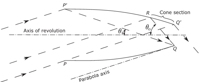
FIGURE 5.4 The в,в0 concentrator; as shown, 0,= 18° and 0„=5O°.
examining a few special cases that all rays entering at angles less than 0, emerge at less than 0„. This must therefore be an ideal 0,/0„ concentrator with

We can also prove this slightly more laboriously from the geometry of the design; this is done in Appendix D.
Clearly the 2D 0/0o concentrator is an ideal concentrator, since the same reasoning as in Section 4.4 can be applied. In 3D form there will be some losses from skew- rays inside 0, being turned back. We show in Figure 5.5a the transmission-angle curve for a typical case. The transition is as sharp as for a full CPC, but w-hen we compare Figure 5.5b with Figure 4.14, we see that the pattern of rejected rays is quite different.
Although the 2D 0/0n concentrator transmits within ()a all rays incident inside 0,, it does not reject all rays incident outside 0, but transmits some of them outside 0o. The reason for this can be seen by noting that the straight cone section in Figure 5.4 lies outside the continuation of the parabolic section, and this parabolic section is the same as the section of an ordinary CPC with entry angle (),. Thus, some rays outside 0, must be transmitted, and since the concentrator is ideal for rays inside 0,, these extra rays must emerge outside 0r The same applies to the 3D version and the effect of these extra rays is not shown in Figure 5.5a.

FIGURE 5.5 (a) The transmission-angle curve for a 10°/60° concentrator, (b) Rays transmitted and turned back in the 10°/60° concentrator for 10° input angle (see Figure 4.14 for full legend).
The Concentrator for a Source at a Finite Distance
So far we have assumed the source to be at infinity, as in the straightforward application to solar energy collection. There are, however, obviously cases where we should like to collect from a source at a finite distance, and the edge-ray principle enables us to derive the shape very simply (Winston, 1978).
In Figure 5.6, let AA be the finite source and let QQ' be the desired position of the absorber. Then if we apply the edge-ray principle, it is clear that the reflecting surface has the cross section of an ellipse, P'Q, with foci at A and Q. For a 3D system the complete surface would be obtained by rotating this ellipse about the axis of symmetry.
We can show that as a 2D system this has maximum theoretical concentration by noting that all rays from AA that enter the concentrator do emerge (by the same reasoning as for the basic CPC), and then calculating the dimensions of the system by coordinate geometry. This approach is complicated, partly because of the geometry but also because it is not so easy to define the collecting angle for a source at a finite distance. It is better to use a more physical approach and calculate the etendue at either end of the system.
We take an object AA=2q and an aperture PP' a distance z apart, as in Figure 5.7; if the coordinate у is measured from the center of the aperture, the etendue is

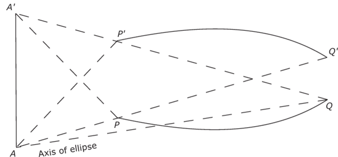

FIGURE 5.7 Calculating the etendue for a source AA' at a finite distance. The collecting aperture is at PP'.
It is useful to rewrite Equation (5.10) in the form

because this version, a remarkably simple result due to Hottel (1954), actually gives the correct etendue formula even when there is no particular symmetry between the relative positions of aperture and source.
Now, returning to Figure 5.6, we know from the fundamental property of the ellipse that the sum of the distances from the two foci to any point on the curve is a constant—that is,

or

so that the etendue measured at the output end is 2Q'Q. Since Q'Q is perpendicular to the axis, this must mean that rays emerge from all points of the exit aperture with their direction cosines distributed uniformly over ±1—that is, this system has the maximum theoretical concentration ratio.
For the 3D case with rotational symmetry (Figure 5.6 now represents a meridional section) a straightforward calculation gives for the etendue (Winston, 1978)

while the maximum value assumed by the skew invariant is

Notice that, just as for the case of an infinitely distant source (0,=constant), both Equations (5.13) and (5.14) are consistent with maximum concentration onto an exit aperture of the diameter given by Equation (5.12). Nevertheless, this system in 3D will turn back some rays, just as for the basic CPC, and so will not be quite ideal.

