Can an Ideal Image-Forming Concentrator Be Designed?
In Section 3.2 we outlined some requirements for ideal image-forming concentrators, and we now have to ask whether they can be designed to fulfill these requirements with useful collection angles.
High-aperture camera lenses are made at about//1.0, but these are complex structures with many components. Figure 3.8 shows a typical example with a focal length of 50 mm. Such a system is by no means aberration-free, and the cost of scaling it up to a size useful for solar work would be prohibitive. Anyway, its numerical aperture is still only about 0.5. The only systems witli numerical apertures approaching the theoretical limit are microscope objectives. Figure 3.9 shows one of the simplest designs of microscope objective of numerical aperture about 1.35, drawn in reverse and with one conjugate at infinity. The image or exit space has a refractive index of 1.52, since it is an oil immersion objective. Such systems have good aberration correction only to about 3° from the axis. Beyond this the aberrations increase rapidly, and also there is less light transmission because of vignetting.[1] The collecting aperture would be about 4 mm in diameter. Again, it would be impracticable to scale up such a system to useful dimensions.
Thus, a quick glance at the state of the art in conventional lens design suggests that imaging concentrators in the form of lens systems wall not be very efficient on a practical scale. Nevertheless, it is interesting to see what might be done with the classical imaging design techniques if practical limitations are ignored.
Roughly, the position seems to be that we cannot design an ideal concentrator— one with the theoretical maximum collection efficiency—using a finite number of lens elements. But, by increasing the number of elements sufficiently or by postulating sufficiently extreme optical properties, we can approach indefinitely close to the ideal. Exceptions to the preceding proposed rule occur in optical systems witli

FIGURE 3.8 A high-aperture camera objective. The drawing is to scale for a 50-mm focal length. The emerging cone of rays has a semiangle of 26° at the center of the field of view.
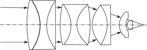
FIGURE 3.9 An oil-immersion microscope objective of high numerical aperture. Such systems can have a convergence angle of up to 60° with an aberration-free field of about ±3°. However, they can only be designed aberration-free for focal lengths up to 2 mm—that is, an actual field diameter of about 200 mm.
spherical symmetry. It has been known since the time of Huygens that a spherical lens element images a concentric surface, as shown in Figure 3.10.
The two conjugate surfaces have radii r/n and nr, respectively. The configuration is used in microscope objectives having a high numerical aperture, as in Figure 3.9. Unfortunately, one of the conjugates must always be virtual (the object conjugate as the figure is drawn), so the system alone would not be very practical as a concentrator. It seems to be true, although this has not been proven, that no combination of a finite number of concentric components can form an aberration-free real image of a real object. However, as we shall see, this can be done with media of continuously varying refractive index. The system of Figure 3.10 would clearly be useful as the last stage of an imaging concentrator. It can easily be shown that the convergence angles are related by the equation

Also, if there is a plane surface terminating in air, the final emergent angle a" is given by


FIGURE 3.10 The aplanatic surfaces of a spherical refracting surface.
Thus, the system could be used in conjunction with another system of relatively low numerical aperture, as in Figure 3.11, to form a fairly well-corrected concentrator. This is, of course, merely a reinvention of the microscope objective of Figure 3.9, and the postulated additional system still needs to operate at about//1 if ordinary materials are used. If we assume some extreme material qualities—say, a refractive index of 4 with adequate antireflection coating for the aplanatic component—then the auxiliary system only needs to be//8 to give nl2 emergent angles in air, as in Figure 3.12.
This is not a difficult requirement. In fact, it is probably true that if we ignore chromatic aberration—that is, if we assume our postulated material of index 4 has no dispersion—this system could be designed in moderate sizes for which the aberrations are indefinitely small over a reasonable acceptance angle.
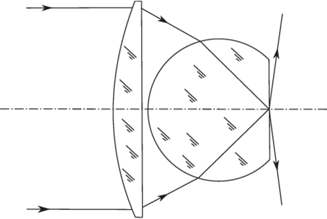
FIGURE 3.11 An image-forming concentrator with an aplantic component.
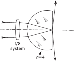
FIGURE 3.12 Use of an aplanatic component of high refractive index to produce a well- corrected optical system.
Ultimately the ray aberrations of optical systems become negligible because the performance, as an imaging system, is limited by diffraction effects. Thus, if an imaging optical system of a certain numerical aperture is used to form an image of a point source and if there are precisely no ray aberrations, the image of the point will not be indefinitely small. It is shown in books on physical optics[2] that the point image will be a blurred diffraction pattern in which most of the light flux falls inside a circle of radius

where X is the wavelength of the light. Notice the first zero of the diffraction pattern (Airy pattern) happens at 1.22 2/D, where D is the size of the aperture. This provides us with a tolerance level for ray aberrations below which we can say the aberrations are negligible. This is sometimes expressed in the form that all of the points in the spot diagram for the aberrations (see Figure 2.10) must fall within a circle of radius given by Equation (3.8).
Another way of setting a tolerance is to say that the wave-front shape as determined by the methods outlined in Section 2.6 would not depart from the ideal spherical shape by more than a specified amount, usually 2/4. Other tolerance systems are also described by Born and Wolf (1975).
Thus, in some way we could arrive at tolerances for the geometrical aberrations such that an imaging concentrator with aberrations inside these tolerances would have ideal performance. Any lens system made with available materials would be impractically complicated and costly if scaled up to a size suitable for solar concentration. But hypothetical materials could be used to bring the aberrations within the diffraction limit with a simple design such as in Figure 3.12.
At this point it might be interesting to consider a different example of a lens system as a concentrator. It is well known that an ellipsoidal solid lens will focus parallel light without spherical aberration, as in Figure 3.13, provided the eccentricity is equal to 1 In. In order to use this as a concentrator we put the entry aperture in front of
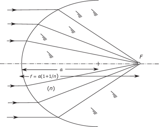
FIGURE 3.13 A portion of an ellipsoid of revolution as a single refracting surface free from spherical aberration. The generating ellipse has eccentricity l//t and semi-major axis a. The figure is drawn to scale with n= 1.81.
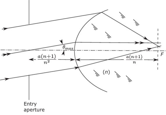
FIGURE 3.14 An ellipsoid of revolution as a concentrator. The entry aperture is set at the first focus of the system.
the ellipsoid, as in Figure 3.14, so that the principal ray emerges parallel to the axis. We find that the ellipsoid has very strong coma of such a sign that all other rays meet the image plane nearer the axis than the principal ray.
Thus, all rays strike within this circle. However, this is not an ideal concentrator, since, as can be seen from the diagram, the radius of this circle is proportional to
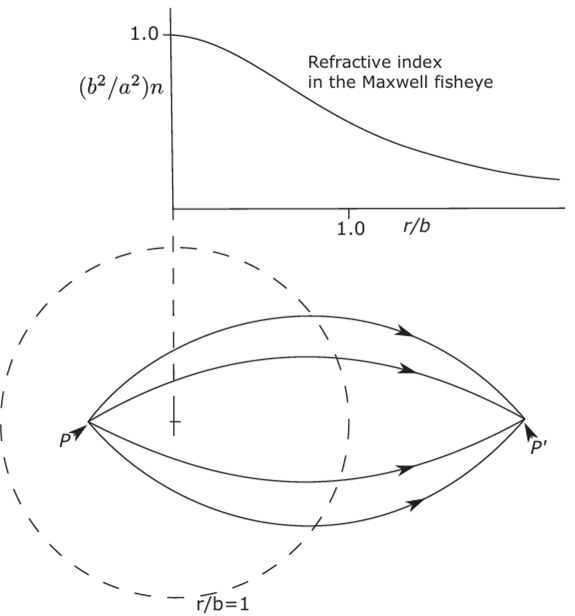
FIGURE 3.15 Rays in the Maxwell fisheye. The rays are arcs of circles.
tan(0max) whereas, according to Equation (3.5), all rays should strike within a circle of radius proportional to sin(0max).[3]
Media with Continuously Varying Refractive Indices
We stated in Section 3.3 that it is thought to be impossible to design an ideal imaging concentrator with a finite number of reflecting or refracting surfaces, even with spherical symmetry, although the example of Figure 3.10 shows that perfect imagery is possible if one conjugate surface is virtual. It has long been known that if we admit continuously varying refractive index, then perfect imagery between surfaces in a spherically symmetric geometry is possible. James Clerk Maxwell (1854) showed that if a medium had the refractive index distribution (Figure 3.15)

where a and b are constants and r is a radial coordinate, then any point would be perfectly imaged at another point on the opposite side of the origin. If a=b= 1, the distances of conjugate points from the origin are related by

immersed in the medium. Luneburg (1964) gave several more examples of media of spherical symmetry with ideal imaging properties. In particular, he found an example, now known in the literature as the Luneburg lens, where the index distribution extends over a finite radius only and where the object conjugate is at infinity. The index distribution is

This distribution forms a perfect point image with numerical aperture unity, as in Figure 3.16, and on account of the spherical symmetry, it can be shown to form an ideal concentrator of maximum theoretical concentration.
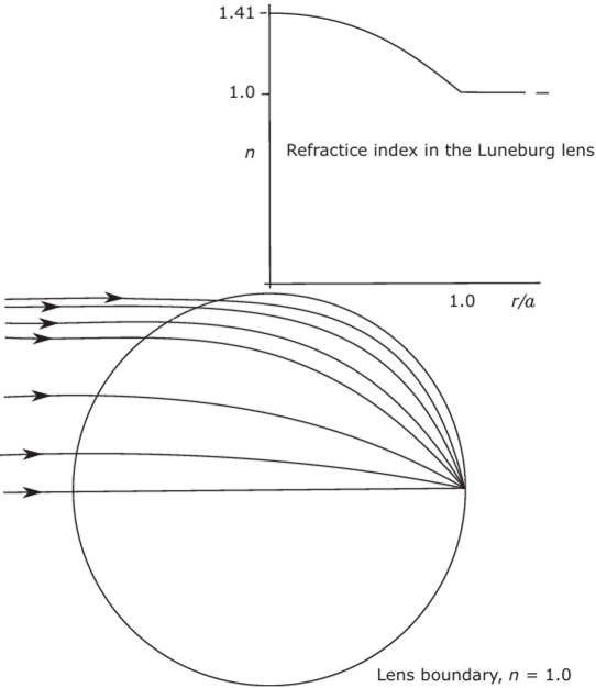
FIGURE 3.16 The Luneburg lens.
Appendix В presents a more detailed treatment that shows how the ray paths are calculated. You can see that the Luneburg lens satisfied Abbe’s sine condition (Equation [3.2]). Also, it follows from the spherical symmetry that perfect point images are formed from parallel rays coming in all directions. It is then possible to consider the Luneburg lens as having the theoretical maximum concentration ratio for any desired collection angle втм up to nl4 but collecting from a concave spherical source at infinity onto a concave spherical absorber attached to the lens. Apart from the practical problem of making the lens this is rather an artificial configuration, since up until now we have been considering plane entry and exit apertures. Yet, the Luneburg lens would have an exit aperture in the form of a spherical cap and an entrance aperture that changes in shape with the angle of the rays. Nevertheless, we show in Appendix В that with reasonable and consistent interpretations of “entrance aperture” and “exit aperture” the Luneburg lens has an optical concentration ratio equal to the theoretical maximum.
Another System of Spherical Symmetry
The discussion in the last section, in which it was suggested that the ideas of concentration could be extended to nonplane absorbers, suggests a way in which the apla- natic imaging system of Figure 3.10 could be used by itself as a concentrator, as in Figure 3.17. The surface of radius aln forms the spherical exit surface, and the internal angle 2a of the cone meeting this face is such that sin «= 1 In. Thus, the emerging rays cover a solid angle 2л, as with the Luneburg lens. The entry aperture is now a virtual aperture on the surface of radius an. The collecting angle 0mM is thus given by sin 0max= 1 In2. The concentration ratio from air to air is n4 for a 3D system—that is, it is determined only by the refractive index. Similarly, the collecting angle is fixed.

FIGURE 3.17 The aplanatic spherical lens as an ideal concentrator; the diagram is to scale for refractive index n = 2; the rays shown emerge in air as the extreme rays in a solid angle 2л.
Thus, this is not a very flexible system, apart from the fact that it has a virtual collecting aperture. But it does have the theoretical maximum concentration ratio, and, if we admit such systems, it is another example of an ideal system.
Image-Forming Mirror Systems
In this section we examine the performance of mirror systems as concentrators. Concave mirrors have, of course, been used for many years as collectors for solar furnaces and the like. Historical material about such systems is given by Krenz (1976). However, little seems to have been published in the way of angle transmission curves for such systems. Consider first a simple paraboloidal mirror, as in Figure 3.18. As is well known, this mirror focuses rays parallel to the axis exactly to a point focus, or, in our terminology, it has no spherical aberration.
However, the off-axis beams are badly aberrated. Thus, in the meridian section (the section of the diagram) it is easily shown by ray-tracing that the edge rays at angle 0 meet the focal plane further from the axis than the central ray, so this cannot be an ideal concentrator even for emergent rays at angles much less than я/2. An elementary geometrical argument (see, e.g., Harper et al., 1976) shows how big the exit aperture must be to collect all the rays in the meridian section.
Referring to Figure 3.19, we draw a circle passing through the ends of the mirror and the absorber (i.e., exit aperture). Then, by a well-known property of the circle, if the absorber subtends an angle 40max at the center of the circle, it subtends 2#max at the ends of the mirror, so the collecting angle is 20max. The mirror is not specified

FIGURE 3.18 Coma of a paraboloidal mirror. The rays of an axial beam are shown in broken line. The outer rays from the oblique beams at angle q meet the focal plane further from the axis than the central ray of this beam.
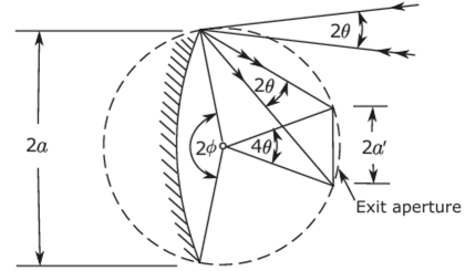
FIGURE 3.19 Collecting all the rays from a concave mirror.
to be of any particular shape except that it must reflect all inner rays to the inside of the exit aperture. Then if the mirror subtends 2ф at the center of the circle, we find

and the minimum value of a' is clearly attained when ф=л/2. At this point the optical concentration ratio is, allowing for the obstruction caused by the absorber,

It can be seen that this is less than 25% of the theoretical maximum concentration ratio and less than 50% of the ideal for the emergent angle used. If, as is usual, the mirror is paraboloidal, the rays used for this calculation are actually the extreme rays—that is, the rays outside of the plane of the diagram all fall within the circle of radius a.
The large loss in concentration at high apertures is basically because the single concave mirror used in this way has large coma—in other words, it does not satisfy Abbe’s sine condition Equation (3.2). The large amount of coma introduced into the image spreads the necessary size of the exit aperture and so lowers the concentration below' the ideal value.
There are image-forming systems that satisfy the Abbe sine condition and have large relative apertures. The prototype of these is the Schmidt camera, which has an aspheric plate and a spherical concave mirror, as showrn in Figure 3.20. The aspheric plate is at the center of curvature of the mirror, and thus the mirror must be larger than the collecting aperture. Such a system would have the ideal concentration ratio for a restricted exit angle apart from the central obstruction, but there would be practical difficulties in achieving the theoretical maximum. In any case a system of this complexity is clearly not to be considered seriously for solar work.
Conclusions on Classical Image-Forming Concentrators
It must be quite clear by now that, whatever the theoretical possibilities, practical concentrators based on classical image-forming designs fall a long way short of the
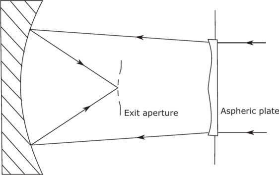
FIGURE 3.20 The Schmidt camera. This optical system has no spherical aberration or coma, so, in principle, it could be a good concentrator for small collecting angles. However, there are serious practical objections, such as cost and the central obstruction of the aperture.
ideal. Our graphs of angular transmission will indicate this for some of the simpler designs. As to theoretical possibilities, it is certainly possible to have an ideal concentrator of theoretical maximum concentration ratio if we use a spherically symmetric geometry, a continuously varying refractive index, and quite unrealistic material properties (i.e., refractive index between 1 and 2 and no dispersion).
This was proved by the example of the Luneburg lens, and Luneburg and others (e.g., Morgan, 1958; Cornbleet, 1976) have shown how designs suitable for perfect imagery for other conjugates can be obtained.
Nevertheless, imaging and nonimaging are not opposite concepts. Only if we restrict ourselves to a finite number of elements can perfect concentrators with plane apertures and axial symmetry not be obtained.
References
Born, M., and Wolf, E. (1975). Principles of Optics, 5th Ed. Pergamon, Oxford.
Cornbleet, S. (1976). Microwave Optics. Academic Press, New York.
Harper, D. A., Hildebrand, R. H., Pernic, R., and Platt, R. (1976). Heat trap: An optimised far infrared field optics system. Appl. Opt. 15, 53-60.
Krenz, J. H. (1976). Energy Conversion and Utilization. Allyn & Bacon, Rockleigh, NJ. Luneburg, R. K. (1964). Mathematical Theory of Optics. University of California Press, Berkeley, CA. This material was originally published in 1944 as loose sheets of mimeographed notes and the book is a word-for-word transcription.
Maxwell, J. C. (1958). On the general laws of optical instruments. Q. J. Pure Appl. Math. 2, 233-247.
Morgan, S. P. (1958). General solution of the Luneburg lens problem. ./. Appl. Phys. 29, 1358-1368.
- [1] Vignetting is caused by rims of components at either end of a long system shearing against each otheras the system is turned off-axis.
- [2] See, for example. Born and Wolf, 1975.
- [3] In fact, on account of the curvature of the ellipse, the radius is even slightly greater than a value proportional to tan(0„m).

