Some Designs of Image-Forming Concentrators
Introduction
In this chapter we examine image-forming concentrators of conventional form— paraboloidal mirrors, lenses of short focal length, and so forth—and estimate their performance. Then we shall show how the departure from ideal performance suggests a principle for the design of nonimaging concentrators—the “edge-ray principle,” as we shall call it.
Some General Properties of Ideal Image-Forming Concentrators
In order to fix our ideas, we use the solar energy application to describe the mode of action of our systems. The simplest hypothetical image-forming concentrator would then function as in Figure 3.1. The rays are coded to indicate that rays from one direction from the sun are brought to a focus at one point in the exit aperture—that is, the concentrator images the sun (or other source) at the exit aperture. Notice that the rays entering the concentrator at a certain angle positive в, marked with the single arrow, will end up at the bottom imaging point at the exit. In other words, the rays from the upper edge of the infinitely far away object are arriving the bottom pixel of the image.
If the exit medium is air, then the exit angle в must be nl2 for maximum concentration. Such a concentrator may in practice be constructed with glass or some other medium of refractive index greater than unity forming the exit surface, as in Figure 3.2. Also, the angle в in the glass would have to be such that sin#= l/n so that the emergent rays just fill the required nl2 angle. For typical materials the angle в would be about 40°.
Figure 3.2 brings out an important point about the objects of such a concentrator.
We have labeled the central or principal ray of the two extreme angle beams a and b, respectively, and at the exit end these rays have been drawn normal to the exit face. This would be essential if the concentrator were to be used with air as the final medium, since, if rays a and b were not normal to the exit face, some of the extreme angle rays would be totally internally reflected (see Section 2.2), and thus the concentration ratio would be reduced. In fact, the condition that the exit principal rays should be normal to what, in ordinary lens design, is termed the image plane is not usually fulfilled. Such an optical system, called telecentric, needs to be specially

FIGURE 3.1 An image-forming concentrator. An image of the source at infinity is formed at the exit aperture of the concentrator.
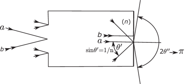
FIGURE 3.2 In an image-forming concentrator of maximum theoretical concentration ratio the final medium in the concentrator would have to have a refractive index n greater than unity. The angle в in this medium would be arcsin (1 In), giving an angle я/2 in the air outside.
designed, and the requirement imposes constraints that would certainly worsen the attainable performance of a concentrator. We shall therefore assume that when a concentrator ends in glass of index n, the absorber or other means of utilizing the light energy is placed in optical contact wit It the glass in such a way as to avoid potential losses through total internal reflection. An alternative configuration for an image-forming concentrator would be as in Figure 3.3. The concentrator collects

FIGURE 3.3 An alternative configuration of an image-forming concentrator. The rays collected from an angle в form an image of the entrance aperture at the exit aperture.
rays over 0max as before, but the internal optics form an image of the entrance aperture at the exit aperture, as indicated by the arrow coding of the rays. This would be in optics terminology a telescopic or afocal system. Such systems simply move the object from infinitely far away to position of finite distance. Naturally, the same considerations about using glass or a similar material as the final medium holds as for the system of Figures 3.1 and 3.2, and there is no difference between the systems as far as external behavior is concerned, witli regards to the possible exit angles and without any loss introduced by the total internal reflections.
If the concentrator terminates in a medium of refractive index n, we can gain in maximum concentration ratio by a factor n or n2, depending on whether it is a 2D or 3D system, as can be seen from Equations (2.13) and (2.14). This corresponds to having an extreme angle в'=nil in this medium. We then have to reinstate the requirement that the principal rays be normal to the exit aperture, and we also have to ensure that the absorber can utilize rays of such extreme angles.
In practice there are problems in using extreme collection angles approaching в=л!2 whether in air or a higher-index medium. There has to be very good matching at the interface between glass and absorber to avoid large reflection losses of grazing- incidence rays, and irregularities of the interface can cause losses through shadowing. Therefore, we may well be content with values of O’ of, say, 60°. This represents only a small decrease from the theoretical maximum concentration, as can be seen from Equations (2.14) and (2.15).
Thus, in speaking of ideal concentrators we can also regard as ideal a system that brings all incident rays within 6>max out within 0',ax and inside an exit aperture a' given by Equation (2.12)—that is, a' = na sin 0max /n'sin0,'uix. Such a concentrator would be ideal, but it will not have the theoretical maximum concentration.
The concentrators sketched in Figures 3.1 and 3.2 clearly must contain something like a photographic objective witli very large aperture (small/-number), or perhaps a high-power microscope objective used in reverse. The speed of a photographic objective is indicated by its /-number or aperture ratio. Thus, an//4 objective has a focal length four times the diameter of its entrance aperture. This description is not suitable for imaging systems in which the rays form large angles approaching nil with the optical axis for a variety of reasons. It is found that in discussing the resolving power of such systems the most useful measure of performance is the numerical aperture or №4, a concept introduced by Ernst Abbe in connection with the resolving power of microscopes. Figure 3.4 shows an optical system witli an entrance aperture of diameter 2a. It forms an image of the axial object point at infinity and the semiangle of the cone of extreme rays is a 0max. Then the numerical aperture is defined by

where n' is the refractive index of the medium in the image space. We assume that all the rays from the axial object point focus sharply at the image point—that is, there is (to use the terminology of Section 2.4) no spherical aberration. Then Abbe showed that off-axis object points will also be sharply imaged if the condition

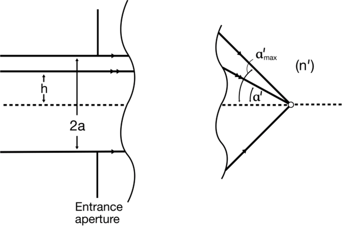
FIGURE 3.4 The definition of the numerical aperture of an image-forming system. The NA is n' sin a'.
is fulfilled for all the axial rays. In this equation h is the distance from the axis of the incoming ray, and a' is the angle at which that ray meets the axis in the final medium. Equation (3.2) is a form of the celebrated Abbe sine condition for good image formation. It does not ensure perfect image formation for all off-axis object points, but it ensures that aberrations that grow linearly with the off-axis angle are zero. These aberrations are various kinds of coma. The condition of freedom from spherical aberration and coma is called aplanatism.
Clearly, a necessary condition for our image-forming concentrator to have the theoretical maximum concentration—or even for it to be ideal as an image-forming system (but without theoretical maximum concentration)—is that the image formation should be aplanatic. This is not, unfortunately, a sufficient condition.
The constant in Equation (3.2) has the significance of a focal length. The definition of focal length for optical systems with media of different refractive indices in the object and image spaces is more complicated than for the thin lenses discussed in Chapter 2. In fact, it is necessary to define two focal lengths, one for the input space and one for the output space, where their magnitudes are in the ratio of the refractive indices of the two media. In Equation (3.2) it turns out that the constant is the input side focal length, which we shall denote by f
From Equation (3.2) we have for the input semiaperture

and also, from Equation (2.118),

By substituting from Equation (3.3) into Equation (3.4) we have

where 0max is the input semiangle. To see the significance of this result we recall that we showed that in an aplanatic system the focal length is a constant, independent of the distance h of the ray from the axis used to define it. Here we are using the generalized sense of “focal length” meaning the constant in Equation (3.2), and aplanatism thus means that rays through all parts of the aperture of the system form images with the same magnification. Thus, Equation (3.5) tells us that in an imaging concentrator with maximum theoretical concentration the diameter of the exit aperture is proportional to the sine of the input angle. This is true even if the concentrator has a numerical exit aperture less than the theoretical maximum, n', provided it is ideal in the sense just defined.
From the point of view of conventional lens optics, the result of Equation (3.3) is well known. It is simply another way of saying that the aplanatic lens with the largest aperture and with air as the exit medium is//0.5, since Equation (3.5) tells us that a=f The importance of Equation (3.5) is that it tells us something about one of the shape-imaging aberrations required of the system—namely distortion. A distortion- free lens imaging onto a flat field must obviously have an image height proportional to tan в, so our concentrator lens system is required to have what is usually called barrel distortion. This is illustrated in Figure 3.5. Our picture of an imaging concentrator is gradually taking shape, and we can begin to see that certain requirements of conventional imaging can be relaxed.
Thus, if we can get a sharp image at the edge of the exit aperture and if the diameter of the exit aperture fulfils the requirement of Equations (3.3)-(3.5), we do not need perfect image formation for object points at angles smaller than 0max. For example, the image field perhaps could be curved, provided we take the exit aperture in the plane of the circle of image points for the direction 0max, as in Figure 3.6. Also, the inner parts of the field could have point-imaging aberrations, provided these were not so large as to spill rays outside the circle of radius a'. Thus, we see that an image-forming concentrator need not, in principle, be as difficult to design as an imaging lens, since the aberrations need to be corrected only at the edge of the field. In practice this relaxation may not be very helpful because the outer part of the field is the most difficult to correct. However, this leads us to a valuable principle for nonimaging concentrators. Not only is it unnecessary to have good aberration correction except at the exit rim, but we do not even need point imaging at the rim itself. It is only necessary that rays entering at the extreme angle #max leave from some point at the rim and that the aberrations inside do not push rays outside the rim of the exit aperture. We shall return to this edge-ray principle later in connection with nonimaging concentrators. The above arguments need only a little modification to apply to the alternative configuration of an imaging concentrator in Figure 3.3, in which the entrance aperture is imaged at the exit aperture. Referring to Figure 3.7, we can imagine that the optical components of the concentrator are forming an image at the exit aperture of an object at a considerable distance, rather than at infinity, and that this object is the entrance aperture. Alternatively, we can imagine that part of the
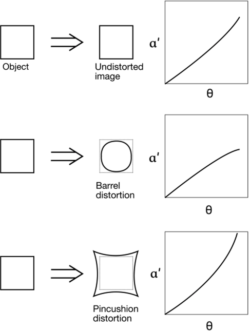
FIGURE 3.5 Distortion in image-forming systems. The optical systems are assumed to have symmetry about an axis of rotation.

FIGURE 3.6 A curved image field with a plane exit aperture.
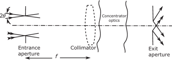
FIGURE 3.7 An afocal concentrator shown as tw'o image-forming systems.
concentrator is a collimating lens of focal length f shown in broken line in the figure, and that this projects the entrance aperture to infinity with an angle subtending 2a/f. The same considerations as before then apply to the aberration corrections.

