A Paradigm for a Wave Description of Optical Measurements
Introduction
Radiance, which is the density of radiative power in phase space, has been the subject of a rich literature over the past 40 years and more (Littlejohn & Winston, 1993; Walther, 1973; Wolf, 1978). It is a tribute to the work of Adrian Walther, Emil Wolf, and many others that the development of a wave theory of radiance, known as “generalized radiance,” continues to the present time. This chapter is complementary to this line of development in that we attempt to bridge the gap between theory and practical radiometry. Radiometric measurements are important in many branches of science and technology. For example, in illumination engineering, the visibility of displays is quantified by radiometers. In astrophysics, radiometry in the far-infrared has played a critical role in understanding the large space-time structure of the universe (Mather, Toral, & Hemmati, 1986). Of course, in the short wave length limit where diffraction effects can be neglected, geometrical optics suffices and one can dispense with the technical difficulties that the wave property of light introduces. But it is precisely in the regime where diffraction effects cannot be neglected that the properties of the measuring instrument have to be taken into account. Moreover, in the absence of a consistent formalism which does take the diffraction property of the instrument into account, it may be difficult to assess the significance of such effects. “Back of the envelope” estimates of diffraction effects may not be reliable and the practical radiometer is left w'ith little guidance as to the magnitude of such effects. For example, an excellent text on radiometry famously states that diffraction effects are “beyond the scope” of the book. In papers (Sun et ah, 2002; Winston, Sun, & Littlejohn, 2002) we have shown how the measurement of radiance can be understood in terms of the statistical properties of the electromagnetic field and the properties of the instrument. However, the utility of this approach was limited by the availability of accessible instrument functions that represent the measuring apparatus. In the process we exhibited a remarkable analogy between the result of measuring radiance and the van Cittert-Zernike (VCZ) theorem. In this chapter we first give an overview of a wave description of the measurement of radiance, referring details to previous publications. This approach is validated by experimental results with highly sophisticated radiometers. The excellent agreement with the analytical model suggests that while our demonstration was confined to the measurement of radiance, it is likely that similar considerations apply to a wide class of optical measurements, where diffraction effects are significant.
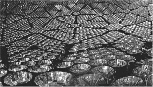
FIGURE 10.1 Nonimaging collectors in the Sudbury neutrino detector in the Sudbury Neutrino Observatory.
We have seen that the concept of etendue plays a central role in nonimaging optics. It is therefore natural to give etendue a wave theoretic description, since light is a wave phenomenon. The closest connection to traditional optics is the concept of radiance and its measurement. Radiance (or its twin relative “brightness”) is extremely useful in illumination, signal detection, and the like. It is therefore natural to seek a wave basis for its description. In fact, as we will see, diffraction effects can be significant in certain regimes, and need to be properly accounted for in a complete and correct theory of optics. Moreover, radiometry (the science of measuring radiance) is not just a relic of the past, but is very much at the cutting edge of current topics. An example are the 10,000 nonimaging cones (Figure 1) used to collect Cherenkov light in the Sudbury neutrino detector, a recipient of the most recent physics Nobel prize. Figure 10.1 shows a light collecting cone from the СОВЕ far-infrared radiometer (Nobel prize 2006).
The van Cittert–Zernike Theorem
The well-known van Cittert-Zernike theorem states that for an incoherent, qua- simonochromatic source of radiation, the equal-time degree of coherence (two-point correlation function) Г(г,г') is proportional to the complex amplitude in a certain diffraction pattern: the amplitude at 7 is formed by a spherical wave converging to 7' and diffracted by an aperture the same size, shape, and location as the source (Born & Wolf, 1999; Mandel & Wolf, 1995). The source could, for example, be a thermal blackbody followed by a filter that selects a small wavelength range.
A familiar geometry is a circular source. Then, apart from a normalizing factor, Г(г,г') in a transverse plane becomes the well-known Airy diffraction amplitude, Equation (10.1).

where F (x) = 2J{ (j:) / x,k = 2n / A, 0S is the angle subtended by the source at r or r', and where s = |r-r'|. Recall that Г(r,F) has its first zero at 5, = 0.61A / 6S. For a numerical example, we consider terrestrial sunlight. Then 6S is 4.7mrad, so that for A=0.5 mm, s, is approximately 65 mm. This is the scale of the transverse correlation of sunlight.
Measuring Radiance
In a previous paper (Littlejohn & Winston, 1995), we examined the relationship between the generalized radiance and the measuring process. We showed how this process can be quantified by introducing the instrument function, which is a property of the measuring apparatus (Sun et al., 2002; Winston, Sun, & Littlejohn, 2002). We showed that the result of the measurement is represented by the quantity

where M is a nonnegative-definite Hermitian operator that characterizes the measuring apparatus, and Г is the two-point correlation function of the incident light, viewed as an operator. The instrument function itself is a coordinate representation of the measurement operator M—for example, its matrix element or its Weyl transform. The Weyl transform maps an operator to a Wigner function (for a discussion of the Wigner-Weyl formalism in optics, see Littlejohn and Winston, 1995).
It is appropriate to associate Q with the signal. We then derived an analytical form for the instrument function for a simple radiometer in one space dimension.
One difficulty in using Equation (10.2) is that it may not be easy to compute the instrument function. Although the one-dimensional calculation in Littlejohn and Winston (1995) was not too hard, we do not expect it to be easy to compute the instrument function for many realistic radiometers, which are two-dimensional in cross section and which may have complicated geometry. Therefore, we have considered other means for determining the instrument function. In a previous publication (Winston & Littlejohn, 1997) we considered the possibility that the instrument function could be measured. In this chapter we present an alternative approach. That is, we point out a physical interpretation of the instrument function that is similar to the van Cittert-Zernike theorem. We do this initially by working through the example of a simple “pinhole” radiometer, and then we comment about generalizations.
Radiance is the power per unit volume in phase space. Therefore, an instrument for measuring radiance (called a radiometer) has to select a window function in phase space. For measurements close to the diffraction limit, the exact shape of the window function is not critical. For this reason we examine a simple radiometer, illustrated in Figure 10.2. The dotted line in the figure is the axis of the radiometer. Light enters from the left and passes through the circular pinhole of radius a. It then passes through a drift space of length L, before passing through another circular aperture of radius b. We assume L » a,b, so the rays are paraxial. The detector is assumed to measure the total power passing through the aperture b and can be thought of as composed of tiny, densely packed, independent absorbing particles (which is a fairly
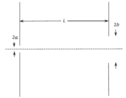
FIGURE 10.2 A pinhole radiometer. The dotted line is the axis. Light enters from the left, passing through circular pinhole a, drift space of length L, and finally circular aperture b.
good approximation to what commonly used detectors like photon detectors, thermal detectors, or photographic film do).
As explained in Littlejohn and Winston (1995) the effect of the radiometer on the radiation field is described by the operator

which maps the wave field at the entrance aperture a into the wave field at the exit aperture b. Here A(a) is the aperture or “cookie cutter” operator representing the pinhole, D(L) is the Huygens-Fresnel operator representing the drift space, and A (b) is the aperture operator for the aperture b. In the approximation L » A the drift operator has the kernel (or matrix element).

where/у = (x,y),r[ = (*',/), r = (x,y,z), r'= {x',y',z'), L = z~z' and /? = |r — r'|
. Here z is the coordinate along the optical axis and it is assumed that z>z'. If in addition we assume rays are paraxial (r,r' <
Following the methods of Littlejohn and Winston (1995), the instrument is represented by the operator M = PP whose matrix elements are
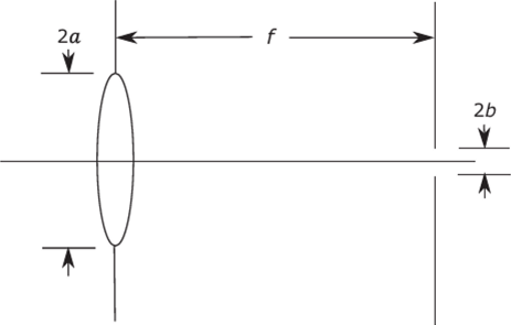
FIGURE 10.3 A practical radiometer. The pinhole is replaced by a lens. The drift space length is essentially the focal length for distant objects La F. where R = |r'-r"|,/?2 =|r-r"|, and the integration is over the detector area. In Equation (10.6) the transverse variables rL and r[ are understood to lie in the entrance plane (the pinhole), so that r±,r[ < a. If this condition is not met, the matrix element is understood to be zero. The expression (10.6) is identical (up to constants) to the mutual intensity evaluated at aperture a of a uniform, delta-correlated source at aperture b (the location of the detector). Thus, to form the van Cittert-Zernike interpretation of the instrument function, we replace the detector (at aperture b, in this example) by a delta-correlated source, and measure the radiation field emanating from the entrance aperture of the instrument (the pinhole in this example). The instrument function (at a given plane) is then proportional to the amplitude at ?' formed by a spherical wave converging to r and diffracted by an aperture the same size, shape, and location as the detector. The detector emulates a delta-correlated source. In a sense, this model involves running the radiometer backwards (exchanging the detector for a source). This interpretation applies also to other radiometers, for example, those with lenses (see Figure 10.3). The essential property is that the operator P’ should serve as a propagator for wave fields traveling to the left (in the negative z direction), just as P serves as a propagator for waves travelling to the right. The situation is rather much like time reversal in quantum mechanics. Not all time evolutions in quantum mechanics are time reversal invariant (only those for which the Hamiltonian commutes with time reversal). In the case of optical fields, it is a kind of “z-reversal” that we need. Lenses, drift spaces, and apertures are “z-reversal invariant,” as long as evanescent waves can be ignored. We remark that the same conditions apply to the usual van Cittert-Zernike theorem.