The Differential Equation for the Concentrator Profile
It is straightforward but laborious to set up a differential equation for the concentrator profile. The equation, given with its solution in Appendix D, is used for the region of the profile that sends extreme rays tangent to the absorber after one reflection— that is, the region between points 2 and 3 in Figure 5.19. The remaining region is an involute arranged to join the profile smoothly, and the equation for this is also given in the appendix. However, it is worth noting that for many practical applications the involute curve can be drawn accurately enough to scale by the draftsman’s method of unwinding a taut thread from the absorber profile.
Mechanical Construction for 2D Concentrator Profiles
In the discussion of Figure 5.19 in Section 5.20, it appeared that part of the concentrator surface was generated as an involute of the absorber section. It is possible to combine this result with the fact that optical path lengths from a wave front to a focus are constant to obtain a simple geometrical construction for the concentrator profile. Figure 5.23 shows a system similar to that shown in Figure 5.19, but we have drawn in a wave front AB of the incoming extreme pencil, and we assume the source is at a large but finite distance. The construction is then as follows. We tie a string between the source and point 1 at the rear of the absorber and pull the string taut with a pencil, as in the so-called gardener’s method of drawing an ellipse. The length of the string must be such that it will be just taut when it is pulled right around the absorber to reach point 1 from the other side, as in Figure 5.24. It is then unwound, keeping the string taut, and the pencil describes the correct profile. To check this, we simply have to show that the line drawn is at the correct angle to produce reflection.
In Figure 5.25 the string is tangent to the absorber at A, the source point is at C, and В is a typical position of the pencil. If the pencil is moved to B' where BCB' is a small angle e, then we have

so that

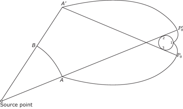
FIGURE 5.23 A concentrator for a source at a finite distance and a nonplane absorber.

FIGURE 5.24 The string construction for the concentrator profile.

FIGURE 5.25 Proof that the string construction gives a concentrator surface that agrees with Fermat’s principle.
Thus, by Fermat’s principle BB' must be a portion of a reflecting surface that reflects CB into BA.
Figure 5.26 shows this method generalized further to a convex source and a convex absorber. The string is anchored at two suitably chosen points A and В and stretched with the pencil P. The length of the string is chosen so that it just reaches to point Q when wound around the absorber. It is easily seen that this generates a 2D ideal concentrator. Here we are generating a concentrator that collects all the flux from the source and sends it all to the absorber, and for this to be physically possible, we must make the perimeters of the source and absorber equal. If this were not so, the construction would not work because the string would not be the correct length to just close the curve, and this would mean we were trying to infringe the rules dictated by conservation of etendue.
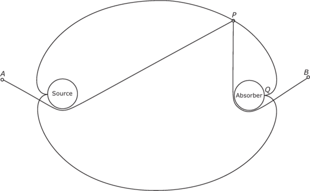
FIGURE 5.26 The case of a convex source and a convex absorber treated by the string construction.
Returning to Figure 5.26 we note that a solution is possible for any distance between source and absorber. We note also that the solution appears not to be unique, in the sense that we could break the reflector at its widest part and insert a straight parallel-sided section of any length, since such a section clearly transforms an eten- due of width 2a and angle л. However, from obvious practical considerations, it is desirable to minimize the number of reflections of a given ray, and this is clearly done by not inserting such a straight section.
We could, of course, vary these solutions still further by adding in CPCs and 0o/0, systems (Section 5.3) at the preceding break points instead of or in addition to the cylindrical sections. Again, this adds to the number of reflections, and it seems that there is always a unique “most economical” solution for which the extreme rays have at most one reflection.
We could generalize the string method to media with a nonuniform refractive index by postulating that the string is elastic in such a way that it always assumes the optical path length, fnds, of the medium through which it passes. There is, of course, no way in which such a string could be realized, but the concept shows how ray trajectories—that is, geodesics—between the extremes of the apertures always define the correct mirror surface.
In another example of parallel development, the “string method” for generating ideal mirror profiles was discovered independently by Bassett and Derrick (1978) of the University of Sidney.
A General Design Method for a 2D Concentrator with Lateral Reflectors
In this section we formulate a more general treatment of the 2D concentrator with lateral reflectors, from which most other results in this chapter could be derived.
A further generalization will be shown in Chapter 6. We shall describe a procedure in which an input surface and an output surface of given shapes are postulated, enclosing and surrounded by regions of given refractive index distributions.
On each of these surfaces a distribution of extreme rays is given. Then the procedure enables us to design a 2D concentrator that will ensure that all rays between the extreme incoming rays and none outside are transmitted so that the concentrator is optimal.
Suppose we have, as in Figure 5.27, two surfaces AB and A'B', and let A В be illuminated in such a way that the extreme angle rays at each point form pencils belonging respectively to wave fronts I, and I,,. Similarly, rays at intermediate angles belong to other wave fronts, so the whole ensemble of rays comes ultimately from a line of point sources and is transformed by a possibly inhomogeneous medium in such a way that the rays just fill the aperture AB. These rays then have a certain etendue H, and we shall see following how to calculate it. Similarly, we draw rays and wave fronts emerging from A’B’ as indicated, and we postulate that these shall have the same etendue H.
Now we want to know how we can design a concentrator system between the surfaces AB and AB’, possibly containing an inhomogeneous medium, that shall transform the incoming beam into the emergent beam without loss of etendue.
To solve this problem, we postulate a new principle (we shall see that our edge-ray principle of Chapter 4 can be regarded as being derived from it): the optical system between AB and AB’ must be such that it exactly images the pencil from the wave front into one of the emergent wave fronts and E/; into the other. By “exactly” we mean that all rays from Z„ as delimited by the aperture AB must just fill AB’ so that none is lost and there is no unused space, and the same for the rays from I/;. This principle is relaxed in the formulation of Chapter 6, where it is only required that the optical system image the rays of u into rays of any of the emergent wave fronts.
At this point it may be objected that the preceding seems to have little connection with our original edge-ray principle. But consider a system such as that in Figure 5.28,

FIGURE 5.27 Beams of equal etendue to fit a concentrator.
which shows rays from one extreme wave front Z„ in a CPC-like concentrator, and also a wave front I,', gradually moving into coincidence with the edge A' of the exit aperture. We then recover the CPC geometry and the original edge-ray principle. Thus, this new principle could be stated in the form that extreme points of the source must be imaged through the system by rays that just fill the exit and entry apertures.
To see how this principle leads to a solution of the general problem stated at the beginning of this section, we must first show how to calculate the etendue of an arbitrary beam of rays at a curved aperture, as in Figure 5.27. We use the Hilbert integral, a concept from the calculus of variations. In the optics context (Luneburg, 1964) the Hilbert integral for a path from PI to P2 across a pencil of rays that originated in a single point is

where n is the local refractive index, к is a unit vector along the ray direction at the current point, and ds is an element along the path P,P2. Thus, 1(1, 2) is simply the optical path length along any ray between the wave fronts that pass through P, and P2, so it is independent of the form of the path of integration. We can now use this to find the etendue of the beams in Figure 5.29. The Hilbert integral from A to В for the a pencil is seen from Equation (6.14) to be

where ф is the angle of incidence of a ray on the line element ds. Thus,

where < > denotes the average and LAB is the length of the curve from A to B.
It follows that, provided the aperture AB is filled with rays from the line of point sources just indicated, the etendue is simply
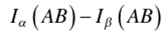
But


FIGURE 5.28 The edge-ray principle as a limiting case of matching wave fronts.

FIGURE 5.29 Calculating the etendue.
where the square brackets denote optical path lengths along the rays so that we obtain, for the etendue,

This result can be seen to be a simple generalization of the result of Equation (5.11).
Now let there be some kind of system constructed that achieves the desired transformation of incident extreme pencils with emergent extreme pencils, as in Figure 5.30. The system takes £„ into Ia. and 2^ into , and we want it to do so without loss of etendue. We write down the optical path length from P,7 to P'a and equate it to that from PB to P„ . Similarly, for the other pencil,

where
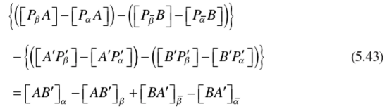
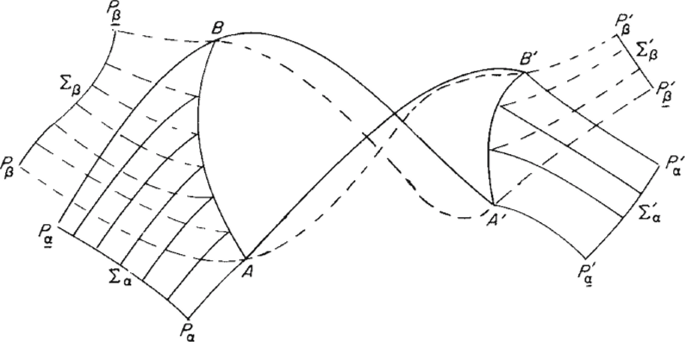
FIGURE 5.30 Rays inside the concentrator.
The left-hand side of this equation can be as the difference between the etendues at the entry and exit apertures. Since we require this difference to vanish, we have to make the right-hand side of the equation equal to zero vanish. A simple way to do this would be to ensure that the optical system of the concentrator is such that the a and /) ray paths from A to B' coincide, and the same for those from В to A'. We can do this by starting segments of mirror surfaces at A and A' in such directions so as to bisect the angles between the incoming a and /? rays. In this way we effectively make the PltA and PflA the same through the optical system between AB and A'B'. In other words, the two extreme rays become one. We then continue the mirror surfaces in such a way as to make all fi rays join up with the corresponding emerging /?' rays; in other words, we image the /? pencil exactly into the ft pencil, and similarly for the other mirror surface connecting В and B'. We have thus completed the construction and used up all degrees of freedom in doing so. This is just one of all the many ways to satisfy Eq. (5.43). Simultaneous Multiple Surfaces (SMS) has been able to also achieve similar results.
A Constructive Design Principle for Optimal Concentrators
We conclude this chapter with a discussion of a design prescription for optimal concentrators that historically has been a fertile source of new and useful solutions. In contrast to the edge-ray principle, which is allied to such abstract notions as etendue and the Hilbert integral theorem, this practical procedure directly instructs us how to draw the profile curve of the mirror. The statement is simply that we maximize the slope of the mirror profile curve consistent with reflecting the extreme entrance rays onto the absorber and subject to various subsidiary conditions that we may wish to impose. This generic principle for designing optimal concentrators is inherent in the earliest references (Hinterberger & Winston, 1966a,b).
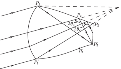
FIGURE 5.31 The solid concentrator that just satisfies the critical angle condition. The profile is hyperbolic from I to P2 (assuming the entry surface is aberration-free). Then if the critical angle вс for total internal reflection is reached at /. it is an equiangular spiral.
To see how this rule operates we notice that the CPC designs for variously shaped absorbers are obtained when we don’t impose any subsidiary conditions. On the other hand, the 0,I0O design results when we impose the condition that the maximum exit angle not exceed 0„. This approach is particularly useful in situations where the subsidiary conditions preclude an ideal system—hence strict application of the edge-ray principle. For example, the various totally internally reflecting designs are obtained by specifying total internal reflection at the external wall as a condition. As discussed earlier in this chapter, when the input ray distribution and index of refraction fall outside a specified range, ideal solutions are not possible. However, efficient designs are still available.
Consider the example in Figure 5.31, where the front entrance face is curved and the index of refraction would not be sufficiently high to totally reflect the extreme rays along the portion P2, P3, were we to follow the edge-ray principle. The maximum slope rule would suggest we maintain a constant angle (the critical angle) between the extreme ray and normal to the wall along this portion of the profile curve. In the approximation that the curve face images the extreme pencil onto a point, the portion between Pb P2 is a hyperbola, whereas the portion between P2, P3 is an arc of an equiangular spiral.
References
Bassett, I. M., and Derrick, G. H. (1978). The collection of diffuse light onto an extended absorber. Opt. Quantum Electron. 10, 61-82.
Hinterberger, H„ and Winston, R. (1966a). Efficient light coupler for threshold Cerenkov counters. Rev. Sci. lustrum. 37, 1094-1095.
Hinterberger, H., and Winston, R. (1966b). Gas Cerenkov counter with optimized light-collecting efficiency. Proc. Int. Conf. Instrum. High Energy Phys. 205-206.
Hottel, H. (1954). Radiant heat transmission. In Heat Transmission, 3rd Ed. (W. H. McAdams, ed.) McGraw-Hill, New York.
Luneburg, R. K. (1964). Mathematical Theory of Optics. University of California Press, Berkeley, CA. This material was originally published in 1944 as loose sheets of mimeographed notes and the book is a word-for-word transcription.
Ortobasi, U. (1974). Proposal to Develop an Evacuated Tubular Solar Collector Utilizing a Heat Pipe. Proposal to National Science Foundation (unpublished). Private communication to the author.
Ploke, M. (1967). Lichtfuhrungseinrichtungen mit starker Konzentrationswirkung. Oplik 25, 31-43.
Rabl, A., Goodman, N. B., & Winston, R. (1979). Practical design considerations for CPC solar collectors. Solar Energy 22(4), 373-381.
Winston, R. (1974). Principles of solar concentrators of a novel design. Sol. Energy 16,89-95.
Winston, R. (1976). Dielectric compound parabolic concentrators. Appl. Opt. 15, 291-292.
Winston, R. (1978). Cone collectors for finite sources. Appl. Opt. 17, 688-689.
Winston, R., and Hinterberger, H. (1975). Principles of cylindrical concentrators for solar energy. Sol. Energy 17,255-258.

