Application to Concentrator Design
We have noted that a mirror surface placed along lines of flow of the vector flux will not disturb the overall flow pattern under a certain condition. This condition is that the zero normal component of J must result from the fact that, for each ray r, incident on one side of the surface, there must be a corresponding ray r2 incident on the other side such that r2 is in the direction of the reflection of r,; we call this a condition of detailed balance of the rays. It is possible to have 7normal = 0 at a surface containing the lines of flow without the condition of detailed balance being fulfilled, and then J would remain undisturbed locally but not over the entire illuminated region. Clearly, the condition of detailed balance holds for a 2D field illuminated by a Lambertian source without obstructions.
We may therefore place mirrors along any of the flowlines of Figure 6.5 without disturbing the flux patterns. For example, suppose we place a mirror along the flowline from Q, ending at the point T where the flowline meets the continuation of the wedge boundary R'Q', and similarly another mirror Q'T symmetrically on the other
side. These mirrors would take the Lambertian flux (|y'| = 2j from QQ' and convert it to a uniform flux with m = 1 at TT. The rays in the emergent beam must spread over an angle ±30°, since у = 1. Clearly, we have constructed a concentrator in reverse, and our construction with parabolas with tilted axes is precisely that for the compound parabolic concentrator.
Since light rays, and therefore flowlines of J , are reversible, we see that a way to construct a concentrator with maximum theoretical concentration is to place mirrors in the flowlines under conditions of detailed balance of the rays.
This constitutes an entirely new perspective on concentrator design.
The Hyperboloid of Revolution as a Concentrator
The results of the previous section lead to another interesting new perspective on the design of nonimaging concentrators. Suppose we start with the disk radiator and we place a mirror in the form of a hyperboloid of revolution coincident with a set of flowlines as in Figure 6.10. We truncate the mirror at some distance so the open end is a circle of diameter AA. Considering the inside as a mirror, this forms a nonimaging concentrator with unusual properties. The foci of the hyperbolas in the section shown are at F and F', the ends of the diameter of the original disk.
Then all rays entering the aperture AA and pointing somewhere inside the disk will be reflected by the mirror so as to strike, eventually, the inner disk of diameter BB'. Thus, the concentrator takes all rays from the virtual source FF', which can pass the entry aperture AA and concentrates them into an exit aperture BB'.
This result is easily proved for rays in a meridional section—that is, in the plane of the diagram. Consider a ray passing through A and aimed at F, as indicated by the double arrow; after the first reflection, it will, by a basic property of conic sections, be aimed at F' and so on as indicated. Thus, the extreme angle rays emerge from the
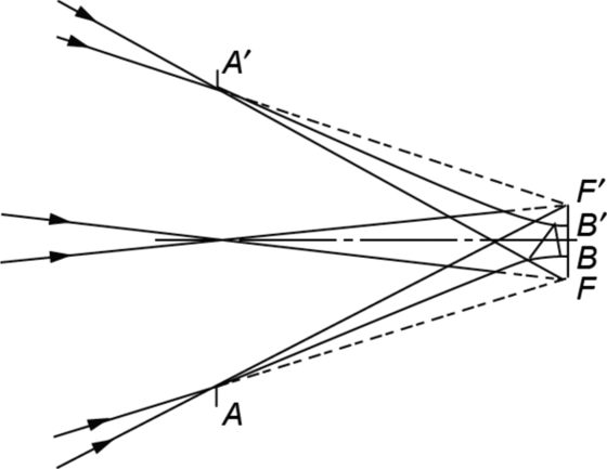
FIGURE 6.10 The hyperboloid of revolution as a concentrator.
exit aperture but only after an infinite number of reflections. It is easily seen that rays at angles inside the extreme angles all emerge. Thus, in the meridional plane this is a concentrator of maximum theoretical concentration.
This property also holds for skew rays, although this is not quite so obvious. We give proof in Appendix F that any skew ray incident on the mirror and pointing on the rim of the disk FF' will be reflected to another point on the rim and the result follows directly. When used in reverse, the same design produces a virtual ring that fills the space between a Lambertian source of diameter BB' and the larger diameter FF'. The visual effect produced is striking.
Elaborations of the Hyperboloid: The Truncated Hyperboloid
The properties of the truncated hyperboloid are evident from the preceding discussion.
We refer to Figure 6.11, where the hyperboloid stops short of the plane of the virtual source. For example, rays collected from the source of diameter FF' by the small aperture will appear to originate from the same source upon emerging from the large aperture. Alternatively, rays directed toward the source of diameter FF' at the large aperture will illuminate the same source upon exiting the small aperture. The truncated hyperboloid may be useful on its own, but usually it is in combination with lenses, as discussed in the following.
The Hyperboloid Combined with a Lens
We have seen that, for the bare hyperboloid, both real and virtual Lambertian sources are in the same plane. This is a limitation in certain applications; however, we can manipulate these positions with lenses to place the sources at more convenient locations. We show in Figure 6.12 the full hyperboloid with a positive lens of diameter AA'=2a at the large aperture, which takes the source plane to infinity—that is, the source is in the focal plane of the lens. Consider the properties of this design. For simplicity we neglect off-axis aberrations of the lens; a complete discussion is found in Welford, O’Gallagher, and Winston (1987). We only remark that, since the requirements on the lens need not be severe (e.g., the focal ratio may be chosen large, as will be shown), the aberrations can be made negligible in practice. In this approximation, the cone of rays of angle 0 is imaged by the lens onto the circle of diameter FF'=2b. The hyperboloid collects the rays that fill this cone and concentrates them into a smaller circle of diameter BB'=2c. We show in Appendix G that da=su. Therefore, this is an ideal concentrator. This result could have been anticipated from
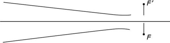
FIGURE 6.11 The truncated hyperboloid of revolution as a concentrator.

FIGURE 6.12 The lens/flow-line concentrator. The entry aperture is FF. and the exit aperture is at the waist of the hyperboloid. The semiangle of the asymptotic cone is clb, and — is the concentration ratio. v c '
the fact that we have postulated an ideal lens while the hyperboloid on its own is an ideal concentrator, albeit operating on a virtual source.
The design considerations readily follow from the geometry of a hyperbola.
With reference to Figure 6.12, the focal ratio of the lens can be estimated from the slope « of the asymptote to the hyperbola. The slope is given by sin a = c / b ; the acceptance angle в determines the focal length of the lens, completing the design.
The Hyperboloid Combined with Two Lenses
We have seen that we can construct a 3D concentrator approaching ideal properties by placing a suitable lens at the large aperture of the hyperboloid. Similarly, we can construct a 3D в{102 concentrator (angle transformer) by placing an additional negative lens at the small aperture of the truncated hyperboloid, which moves the source plane to infinity as shown by Ning (1988). The construction is shown in Figure 6.13, where it is apparent that the focal lengths of the two lenses are related
, F, tan в, , , . , f cosO,
by — =--, whereas their local ratios are related as — =--. We see that
F2 tan в2 f2 cos в2
this design lends itself to all dielectric versions, since the positive and negative lenses are readily molded into the shape of the transformer, whereas in practical cases the condition for total internal reflection is likely to be satisfied.
Generalized Flowline Concentrators with Refractive Components
In 2D it is possible to generalize the flowline construction following the notions expressed in Section 6.4. For simplicity, we confine our discussion to systems that are symmetrical transverse to the optic axis. As already noted in Section 6.4, the

FIGURE 6.13 0,/<92 transformer using an FLC with two lenses.
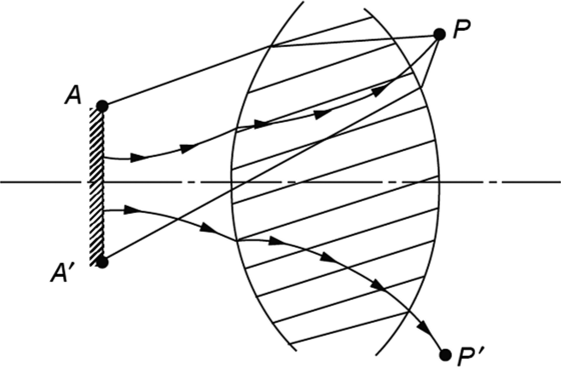
FIGURE 6.14 Flowlines with refractive components AA' are a Lambertian source. The arrows indicate row lines; the plain lines, rays.
etendue H generalizes to the difference of optical path lengths (up to an overall constant). This remains true even in the presence of refractive media, provided the optical path lengths are measured along rays. These rays need not be straight lines. Thus, in Figure 6.14, the etendue H from Lambertian source AA to section PP' is proportional to [A'P] - [AP], where the brackets indicate optical path lengths. It follows that the lines of flow (indicated by arrows in the figure) lie along contours of /7=constant. Since the detailed balance condition holds in 2D, we may construct concentrators by placing mirrors along the flowdines. However, it does not follow that the 3D construction obtained by rotating the 2D flowline about the optic axis will automatically satisfy detailed balance. Specific cases will have to be checked with respect to detailed balance before the usefulness of the 3D designs can be evaluated.
References
Jiang, L., and Winston, R. (2016a). Flow line asymmetric nonimaging concentrating optics. In Nonimaging Optics: Efficient Design for Illumination and Solar Concentration XIII—Commemorating the 50th Anniversary of Nonimaging Optics (Vol. 9955, p. 995501). International Society for Optics and Photonics.
Jiang, L., and Winston, R. (2016b). Thermodynamic origin of nonimaging optics. Journal of Photonics for Energy, 6(4), 047003.
Ning, Xiaohui. (1988). Three-dimensional ideal 0f02 angular transformer and its uses in fiber optics. Appl. Opt. 27(19), 4126-4130.
O’Gallagher, Joseph, Winston, Roland, and Welford, Walter T. (1987). Axially symmetric nonimaging flux concentrators with the maximum theoretical concentration ratio. JOS A A 4(1), 66-68.
Sparrow. E. M., and Cess, R. D. (1978). Radiation Heat Transfer. Hemisphere, Washington. DC.
Winston, R., and Welford, W. T. (1979a). Geometrical vector flux and some new imaging concentrators. J. Opt. Soc. Am. A 69, 532-536.
Winston, R., and Welford. W. T. (1979b). Ideal flux concentrators as shapes that do not disturb the geometrical vector flux field: A new derivation of the compound parabolic concentrator. JOSA 69(4), 536-539.

