The Lens-Mirror CPC
A more fundamental method for overcoming the disadvantage of excessive lengths incorporates refractive elements to converge the pencil of extreme rays. By consistent application of the edge-ray principle we leave the optical properties of the concentrator essentially identical to the all-reflecting counterpart while substantially reducing the length in many cases. The edge-ray principle requires that the extreme incident rays at the entrance aperture also be the extreme rays at the exit aperture. In the all-reflecting construction (Figure 4.10) this is accomplished by a parabolic mirror section that focuses the pencil of extreme rays from the wave front IV onto the point P2 on the edge of the exit aperture. To incorporate, say, a lens at the entrance aperture, the rays from W, after passage through the lens, are focused onto P2 by

FIGURE 5.16 Concentrator surface area as a function of concentration ratio for 2D truncated concentrators. The numbers marked on the curves are the actual truncation ratios—that is, Lj/L.

FIGURE 5.17 Concentrator surface area as a function of concentration ratio for 3D truncated concentrators. The numbers marked on the curves are the actual truncation ratios—that is, Lj/L.
an appropriately shaped mirror M (Figure 5.18). Therefore, the profile curve of M is then determined by the condition

To comprehend the properties of the lens-mirror collector, it is useful to consider a hypothetical lens that focuses rays from P onto a point F. From Equation (5.24) the appropriate profile curve for M is a hyperbola with conjugate foci at F and P2 (Figure 5.18).[1] This example illustrates the principal advantage of this configuration. The overall length is greatly reduced from the all-reflecting case to L=f the focal length of the lens. A real lens would have chromatic aberration, so M would no longer be hyperbolic but simply a solution to Equation (5.24). A solution will be possible as long as the aberrations are not so severe as to form a caustic between the lens and the mirror. For the example in Figure 5.18, where the lens is plano-convex with index of refraction n -1.5, this means we must not choose too small a value for the focal ratio of this simple lens (an//4 choice works out nicely). Alternatively, we may say that the mirror surface corrects for lens aberrations, providing these are not too severe, to produce a sharp focus at P2 for the extreme rays. Of course, this procedure can only be successful for monochromatic aberrations so that it is advantageous to employ a lens material of low dispersion over the wavelength interval of interest.
We may expect the response to skew rays in a rotationally symmetric 3D system to be nonideal just as in the all-reflecting case, and, in fact, ray-tracing of some
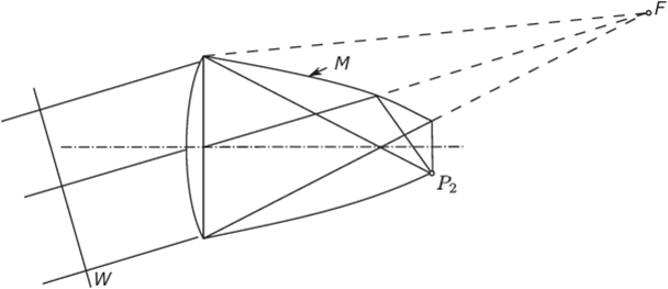
FIGURE 5.18 The lens-mirror CPC.
sample lens-mirror configurations shows angular cutoff characteristics indistinguishable from the simple CPC counterpart. We note that certain configurations of the lens-mirror type were proposed by Ploke (1967).
D Collection in General
For moderate concentration ratios for solar energy collection, there is considerable interest in systems that do not need diurnal guiding for obvious reasons of economy and simplicity (see, e.g., Winston, 1974; Winston & Hinterberger, 1975). These naturally would have trough-like or 2D shapes and would be set pointing south[2] at a suitable elevation so as to collect flux efficiently over a good proportion of the daylight hours. So far our discussion has suggested that these might take the form of 2D CPCs, truncated CPCs, or compound systems with a dielectric-filled CPC as the second stage. In discussing all these it was tacitly assumed that the absorber would present a plane surface to the concentrator at the exit aperture, and this, of course, made the geometry particularly simple. In fact, when applications are considered in detail, it becomes apparent that other shapes of absorber would be useful. In particular, it is obvious that cylindrical absorbers—that is, tubes for heating fluids—suggest themselves. In this chapter we discuss the developments in design necessary to take account of such requirements.
Extension of the Edge-Ray Principle
In Chapter 3 we proposed the edge-ray principle as a way of initiating the design of concentrators with concentration ratios approaching the maximum theoretical value. We found that for the 2D CPC this maximum theoretical value was actually attained by direct application of the principle. We now propose a way of generalizing the principle to nonplane absorbers in 2D concentrators. Let the concentrator be as in Figure 5.19, which shows a generalized tubular absorber. We assume the section of

FIGURE 5.19 Generalizing the edge-ray principle for a nonplane absorber.
the absorber is convex everywhere, and we also assume it is symmetric about the horizontal axis indicated.
Then we assert that the required generalization of the edge-ray principle is that rays entering at the maximum angle в, shall be tangent to the absorber surface after one reflection, as indicated.
The generalization can easily be seen to reduce to the edge-ray principle for a plane absorber. In order to calculate the concentration we need to have a rule for constructing the concentrator surface beyond the point P0', at which the extreme reflected ray meets the surface. Here we choose to continue the reflector as an involute of the absorber surface, as indicated by the broken line. A reason for this choice will be suggested in the following. We shall be able to show that this design for a 2D concentrator achieves the maximum possible concentration ratio, defined in this case as the entry aperture area divided by the area of the curved absorber surface.
Following Winston and Hinterberger (1975) we let r be the position vector of a current point P on the concentrator surface and we take R as the position vector of the point of contact of the ray with the absorber. Then we have

where t is the unit tangent to the absorber—that is, we have

where S is the arc length round the absorber. Let к be a unit vector along the direction of the extreme rays so that in the coordinate system shown k=(sin ()„ 0, -cos в,). Our condition that the tangent to the absorber be reflected into к takes the form, equating sines of the angles of incidence and reflection,

or

Now by differentiating Equation (5.25) we obtain

and on scalar multiplication by t this gives

On substituting in Equation (5.27) and integrating we obtain

In this equation points 2 and 3 would be those corresponding to the extreme reflected rays, as in the diagram.
Between points 1 and 2 we have postulated that the concentrator profile shall be an involute of the absorber, and the condition for this is

Thus, for this section of the curve we have from Equation (5.28)
 or, since our involute is chosen to be the one that starts at point 1
 Thus, Equation (5.29) gives

From the figure it can be seen that (r3 -r2) k is equal to the projection of PoA' onto APu. Thus

and on substituting into Equation (5.32) we find

Recalling that the second section of the concentrator is an involute, we see that l2=S2. Thus,

We have proved that the concentrator profile generated in this way has the theoretical ratio of input area to absorber area—that is, it has the maximum theoretical concentration ratio if no rays are turned back.
If the property of the involute—that its normal is tangent to the parent curve—is remembered, it is easy to see that a concentrator designed in this way sends all rays inside the angle 0, to the absorber, including those outside the plane of the diagram if it is a 2D system. Thus, from arguments based on etendue and on phase space conservation (see Section 2.7 and Appendix A) the system is optimal.
Some Examples
It is easy to apply our generalization to plane absorbers. Figure 5.20 shows an edge- on fin absorber QQ' with extreme rays AQPi and A'QP0. Clearly the section of the concentrator between P0 and P,l is an arc of a circle centered on Q and the section A'PI is a parabola with focus at Q and axis AQP'}.
The two-sided flat plate collector normal to the axis, as in Figure 5.21, is a slightly more complicated case. Following our rules, there are three sections to the profile. OP' receives no direct illumination and is thus an involute of the segment OQ' that is, it is an arc of a circle centered on Q' and therefore part of a parabola with focus at Q and axis AQ'P'. R'A' must focus extreme rays on Q and is therefore a parabola with focus Q and axis parallel to AQ'P'.
In all cases it can easily be seen from the general mode of construction described in Section 5.10 that the segments of different curves have the same slope where they join; for example, in Figure 5.21 the normal at P' is a ray for the circular segment OP' and the parabolic segment P'R', and at R' the incident ray at angle 0I must be reflected to Q' by the segment P'R' and to Q by the segment R'A'.
Figure 5.22 shows to scale the profile for a circular section absorber. Here the actual profile does not have a simple parabolic or circular shape, but we shall give the solution in Section 5.12. It is noteworthy, however, that in Section 5.10 we deduced
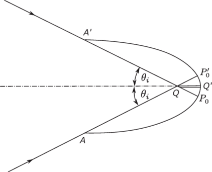
FIGURE 5.20 The optimum concentrator design for an edge-on fin.

FIGURE 5.21 The optimum concentrator design for transverse fin.

FIGURE 5.22 The optimum concentrator design for a cylindrical absorber.
the property of having the maximum theoretical concentration ratio without explicit reference to the profile, just as we were able to do for the basic CPC (see Chapter 4). For example, Ortobasi (1974) independently developed the ideal mirror profile in an innovative collector program at Corning Glass Company.

